Purpose
This work instruction documents the current RADR wireless remote assembly process from prepared PCB and printed parts through final device test.
Use these instructions with the active PCB, printed parts, and BOM release for the build.
Required Parts and Consumables
-
Gather the required parts before starting assembly.
-
Confirm the assembly set includes:
RADR-PCB-assemblyscreenbatteryfront-housingback-housingbattery-flap- 2x
side-button middle-buttonpower-slider-buttonknobweather-stripping- 5x
BC-0408LTFBtri-lobe screws hot-glue
-
If all required parts are present, continue onward.
Tools
- Rasp
- T8 bit for tri-lobe screws
- Electric screwdriver or hand driver
- Isopropyl alcohol
- Microfiber cloth
- Razor blade
- Hot glue gun
- Small screwdriver
Prepare the PCBA
-
Deburr the edges of the
RADR-PCB-assemblywith a rasp until the board edge is smooth.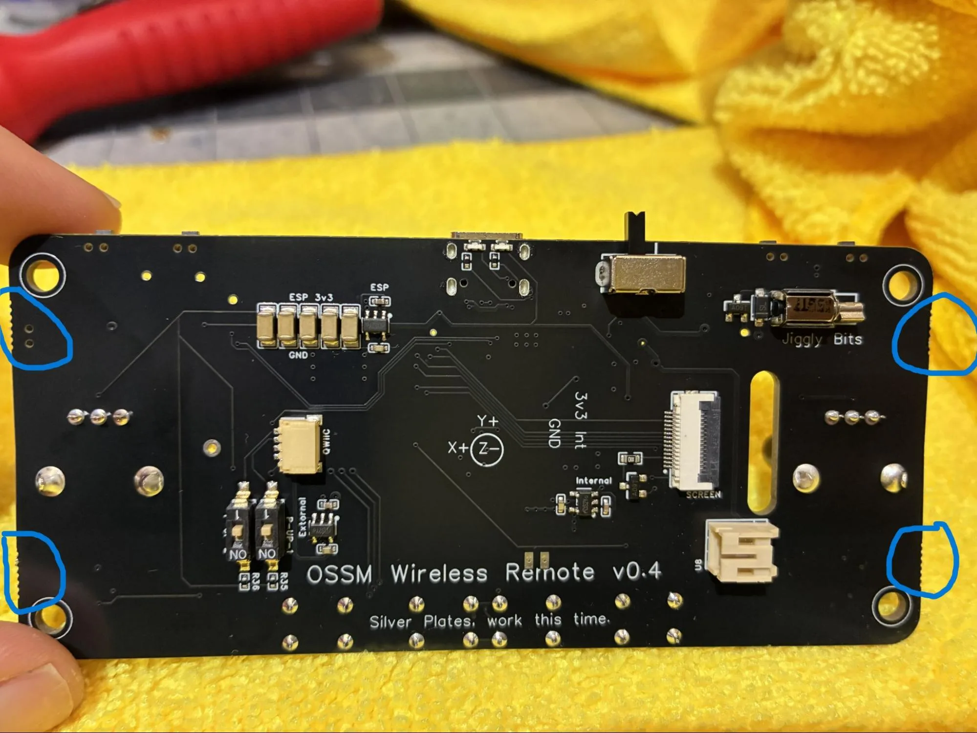
Deburr the PCBA edges until smooth. -
Wipe the marked weather-strip area on the PCBA with
isopropyl-alcoholand amicrofiber-cloth.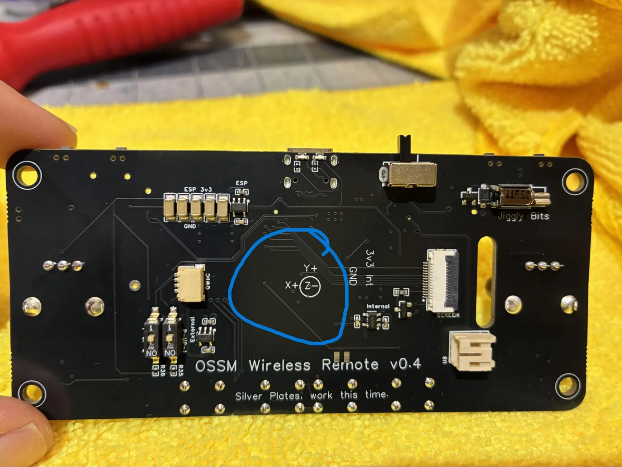
Clean the marked weather-strip area. -
Attach a 2.5 cm piece of
weather-strippingto the center of the cleaned area.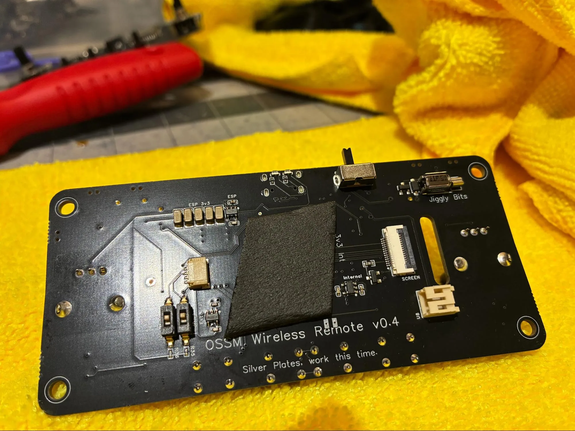
Weather stripping installed on the PCBA. -
Fit the printed
power-slider-buttonover the PCBA on/off switch.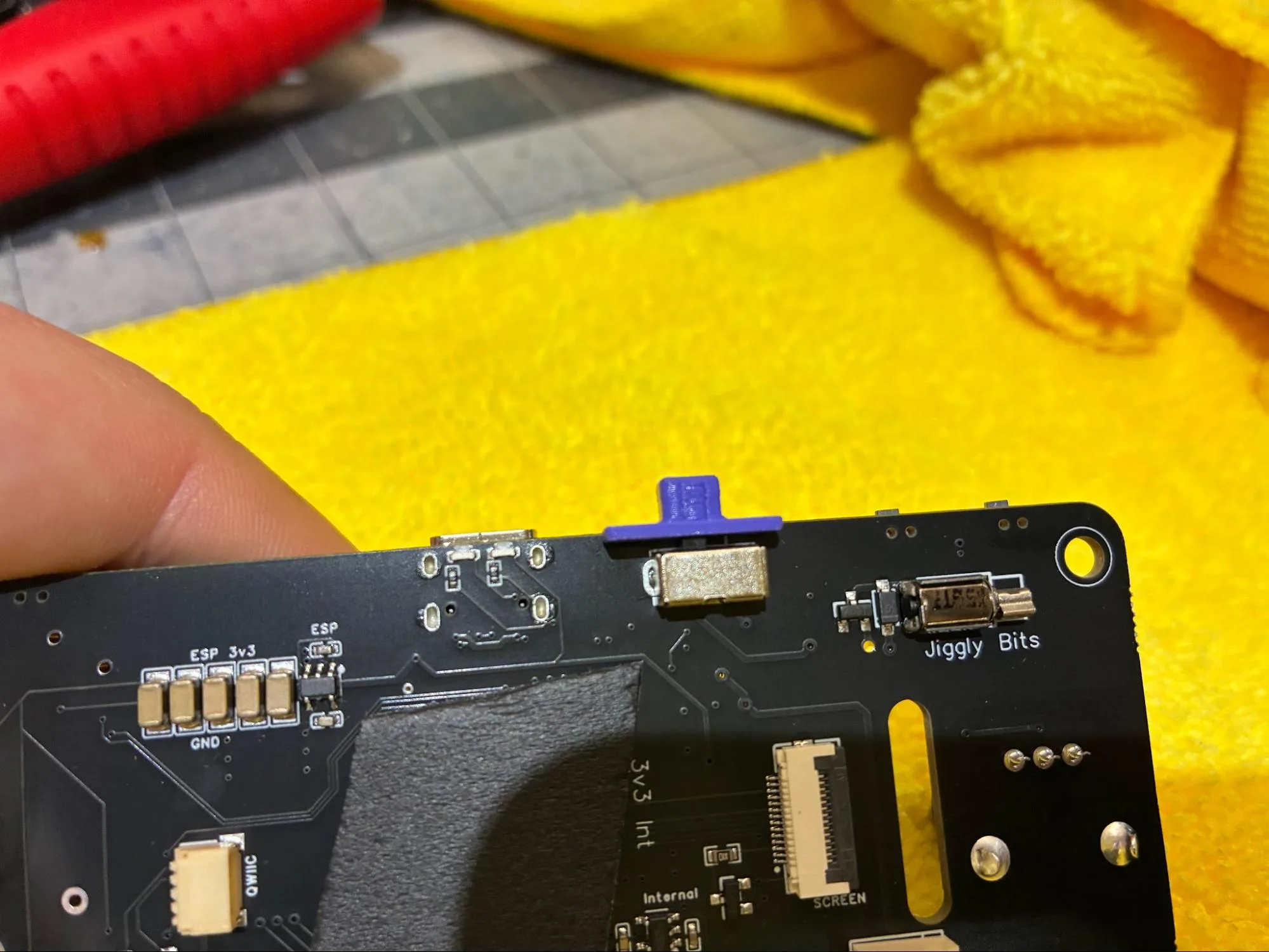
Power switch cover installed. -
Connect the 800 mAh LiPo
batteryto the PCBA.Keep the PCBA switched off after connecting the battery. The PCBA produces a green light when powered on and does not produce that light when switched off.
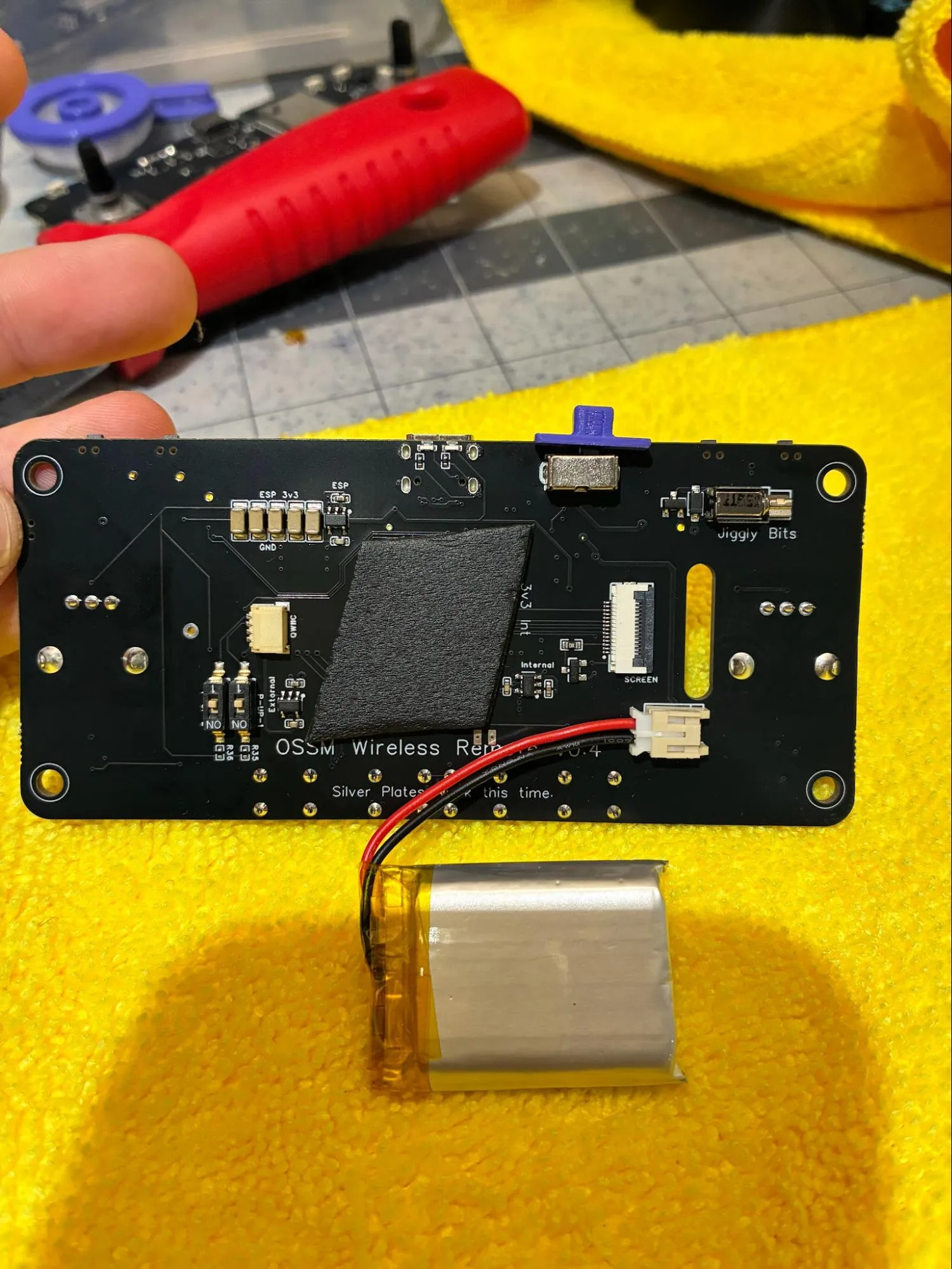
Battery connected to the PCBA. -
Confirm the PCBA is deburred, padded, fitted with the power switch cover, connected to the battery, and switched off before continuing.
Prepare the Front Housing
-
Use a
razor-bladeto cut a small triangle off both bumpers on thefront-housing.These cuts stop the bumpers from catching on the PCBA during installation.
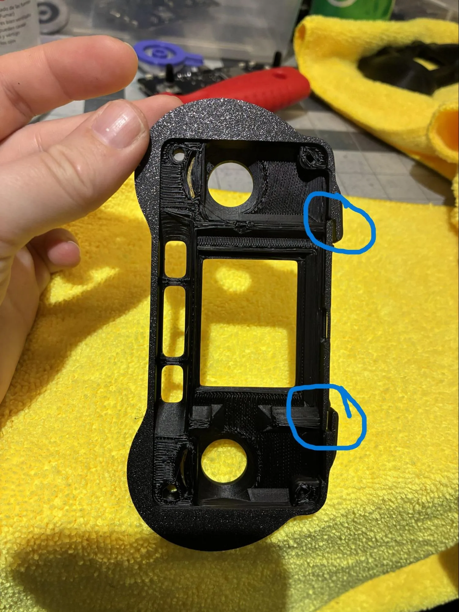
Trim both bumper features. 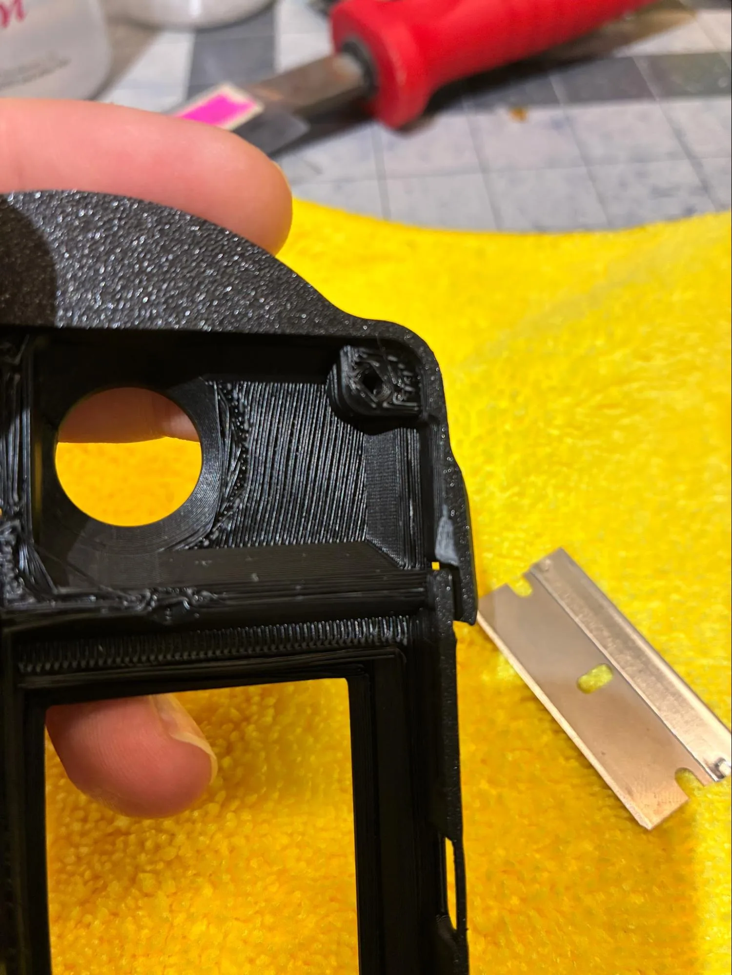
Trimmed interior bumper reference. -
Remove the protective film from the
screen.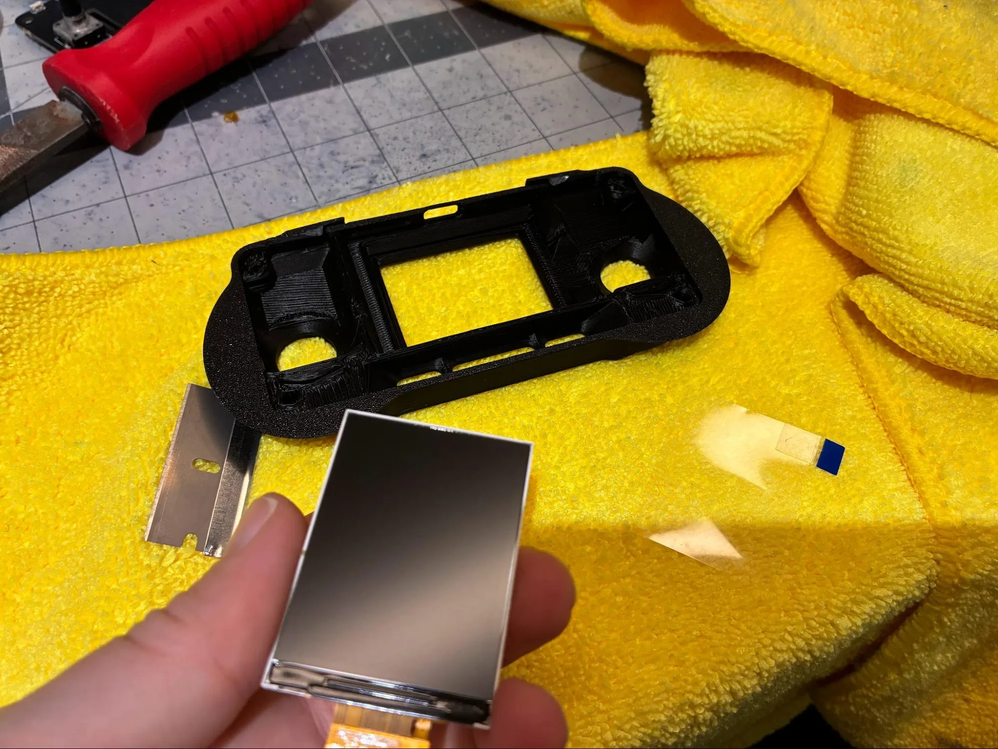
Remove the display film. -
Install the
screeninto thefront-housing.Insert the screen into the bottom lip of the interior front housing first. Gently flex the housing outward while pressing the screen into the upper screen lip. Confirm the screen is flush against the housing.
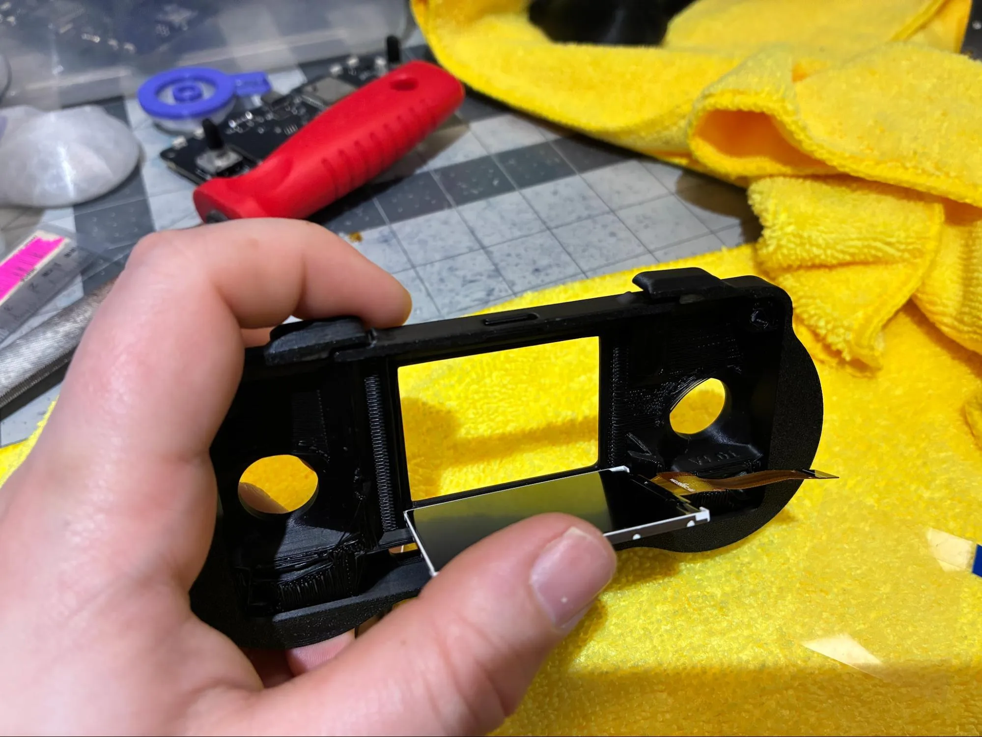
Insert the screen into the bottom lip first. 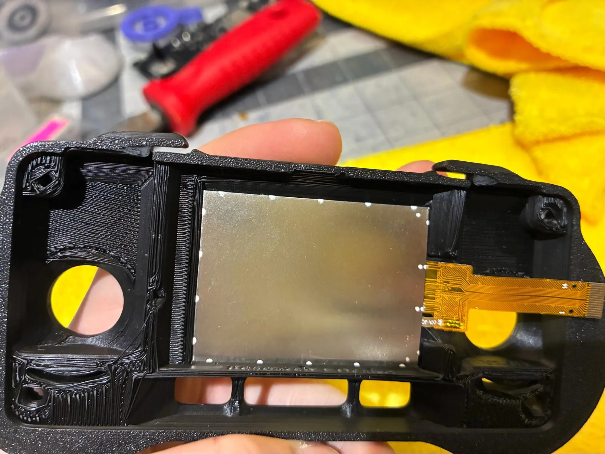
Screen seated flush in the housing. -
Run a thin, low-profile bead of
hot-gluealong the screen edges.Keep the glue bead in contact with both the screen edge and the plastic housing. The housing plastic should melt slightly into the glue.
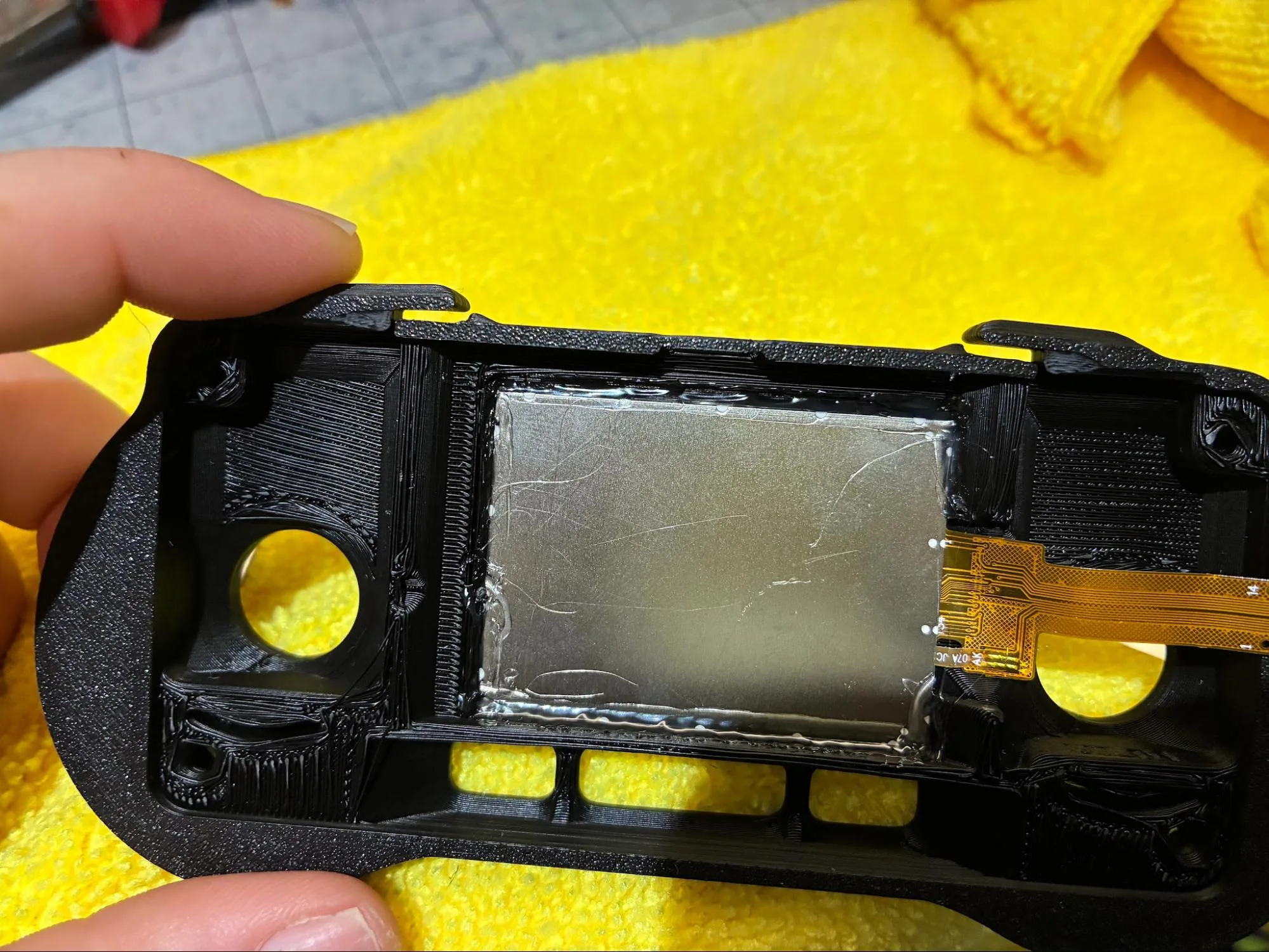
Low-profile glue bead around the screen edge. -
Drop the printed buttons into the
front-housing.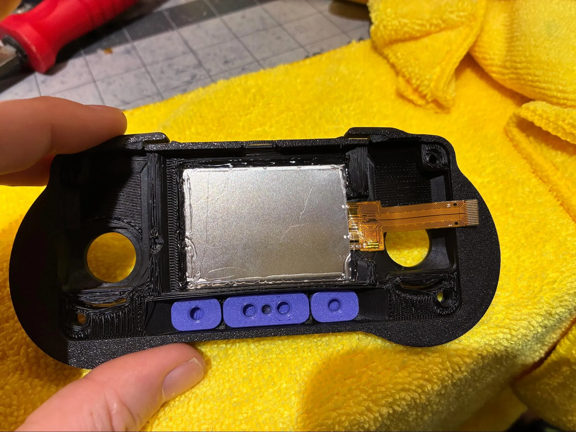
Buttons installed in the front housing. -
Confirm the bumpers are trimmed, the screen is glued in place, and the buttons move freely before continuing.
Install the PCBA
-
Feed the screen ribbon through the cutout in the PCBA, then press the PCBA flush into the
front-housing.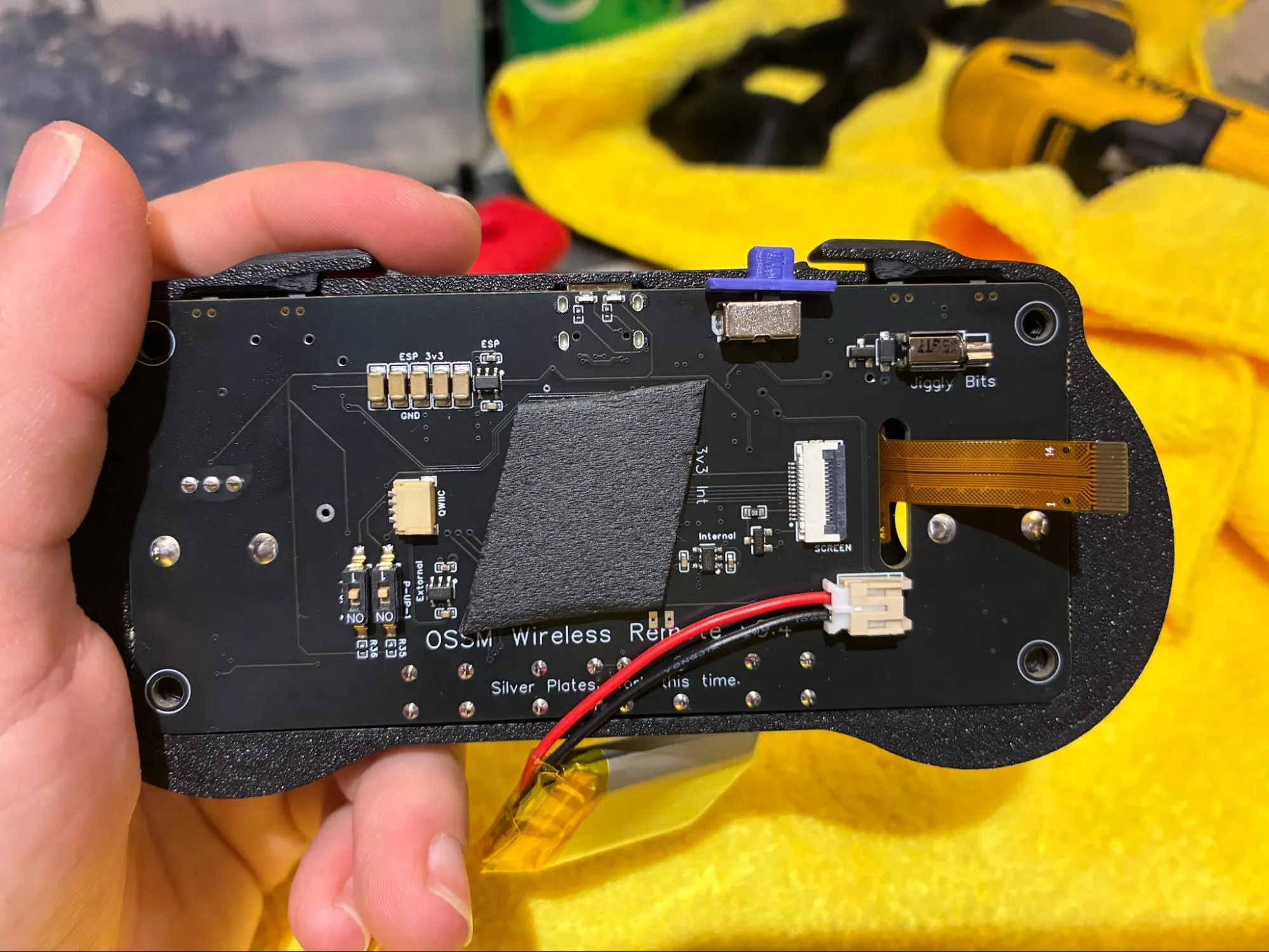
PCBA seated in the front housing. -
Open the screen ribbon connector on the PCBA with a small screwdriver.
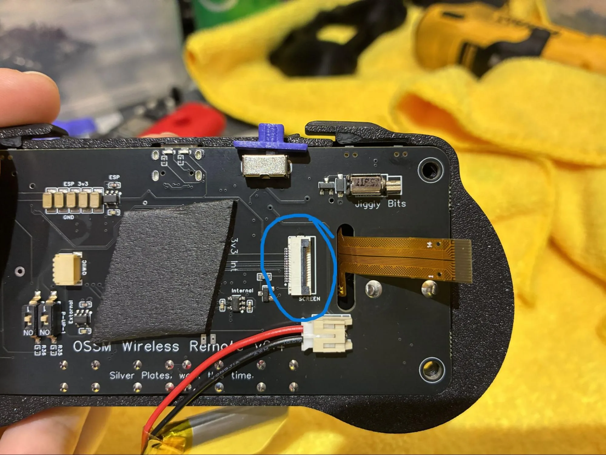
Open the screen connector. -
Insert the screen ribbon into the connector and close the connector.
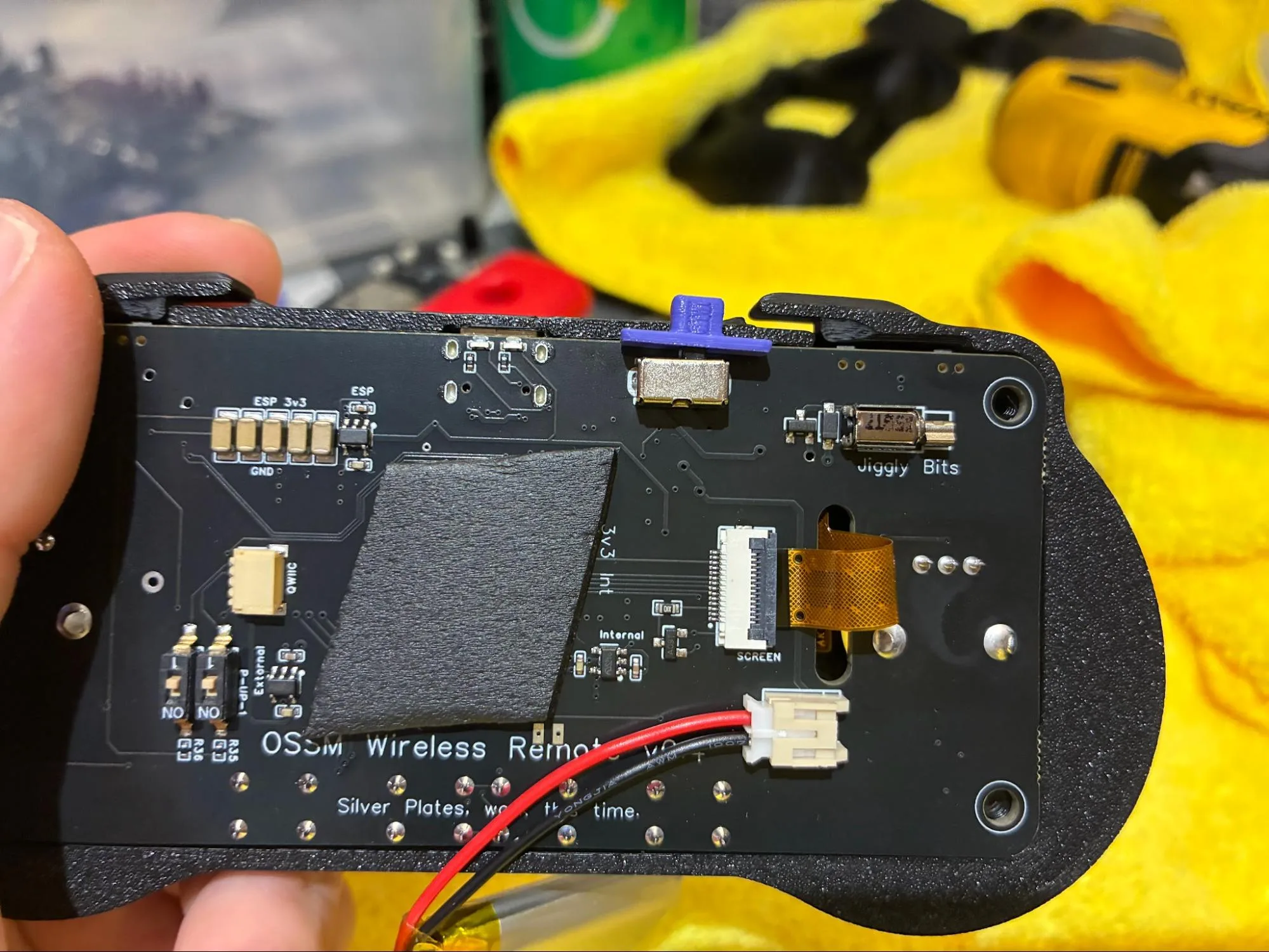
Screen ribbon connected. -
Tuck the screen ribbon into the housing.
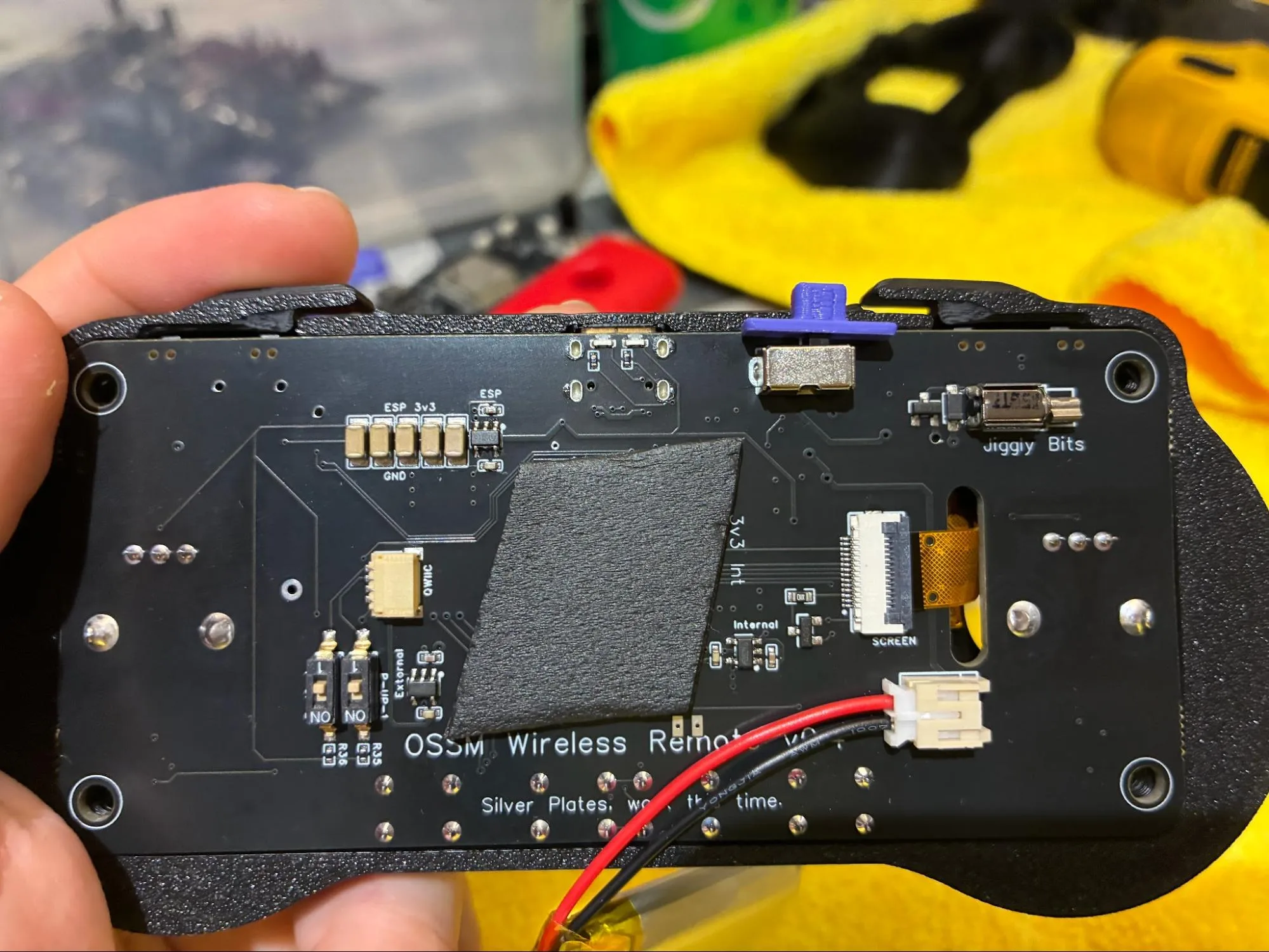
Screen ribbon tucked into the housing. -
Confirm the PCBA sits flush, the ribbon connector is closed, and the ribbon is tucked away from pinch points before continuing.
Close the Housing
-
Place the
back-housingover thefront-housingby inserting the on/off switch into its cutout.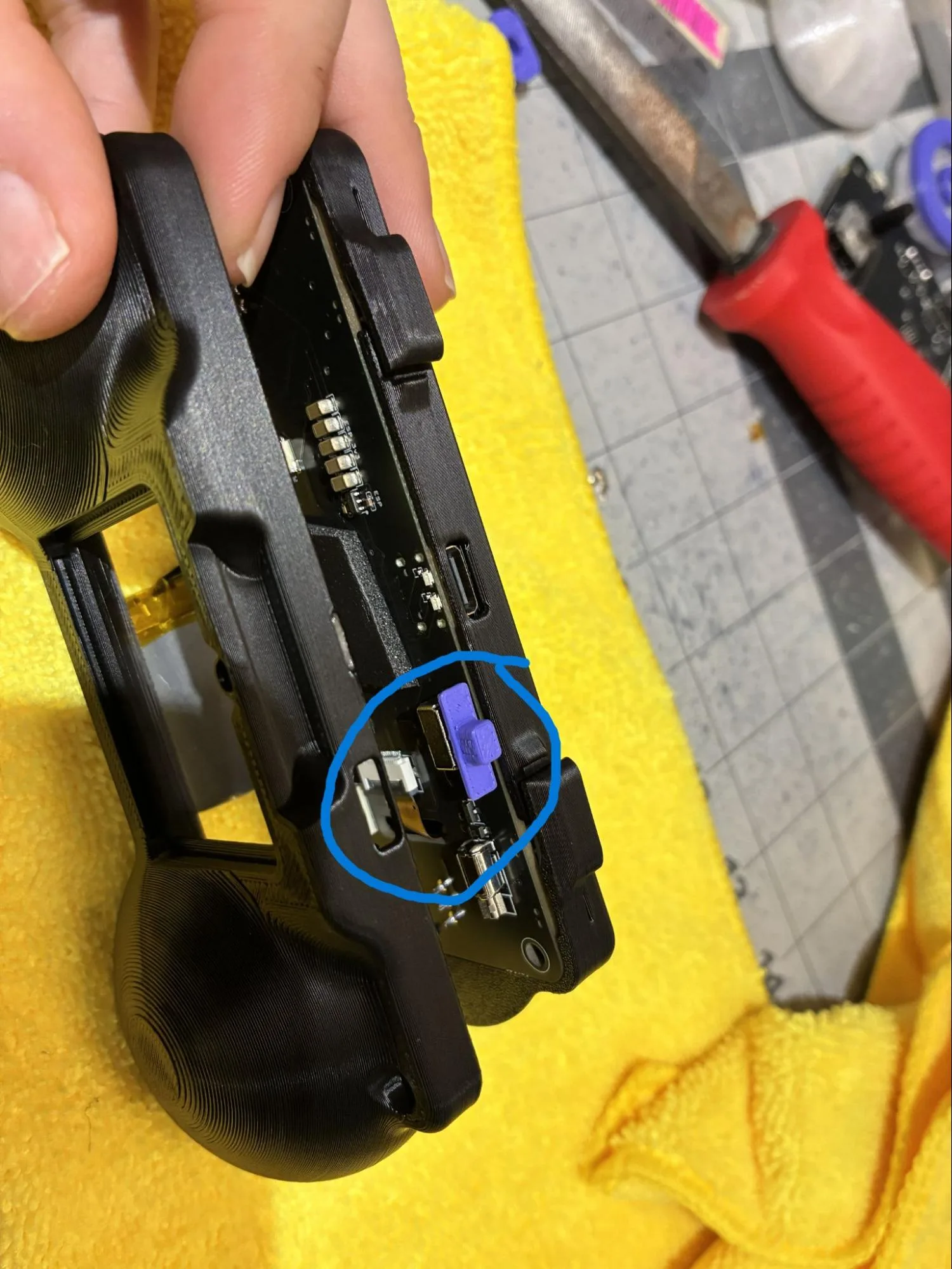
Align the power switch with the back-housing cutout. -
Pull the
batterythrough the open space in the back housing that will become the battery compartment.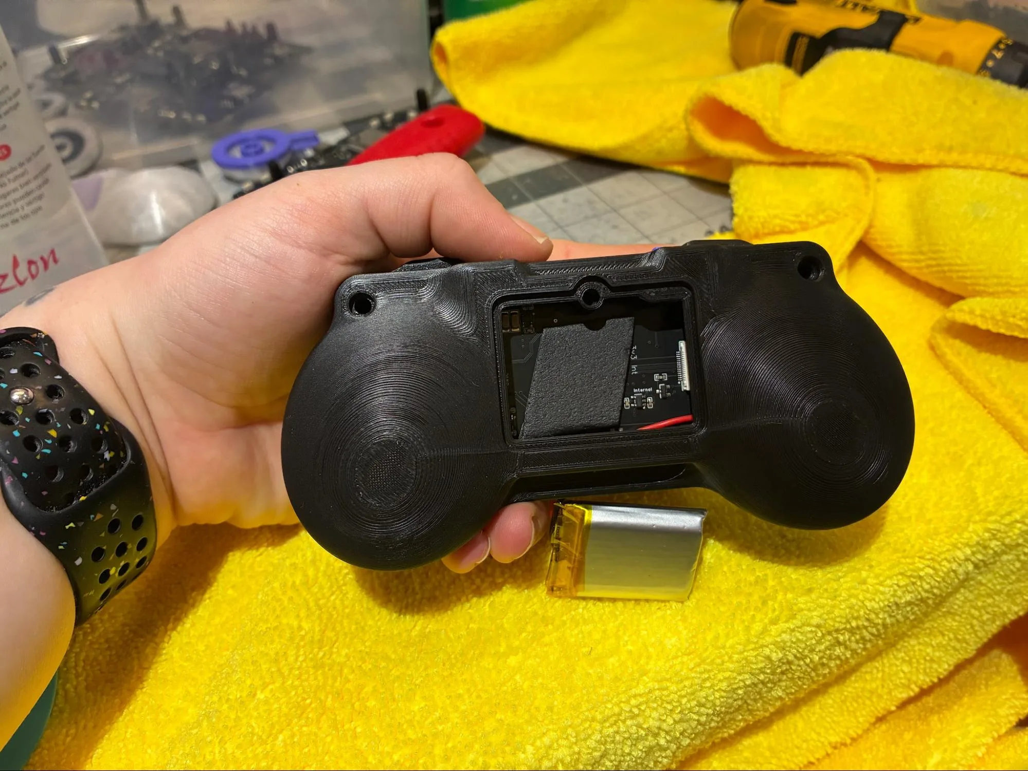
Pull the battery through the battery compartment opening. 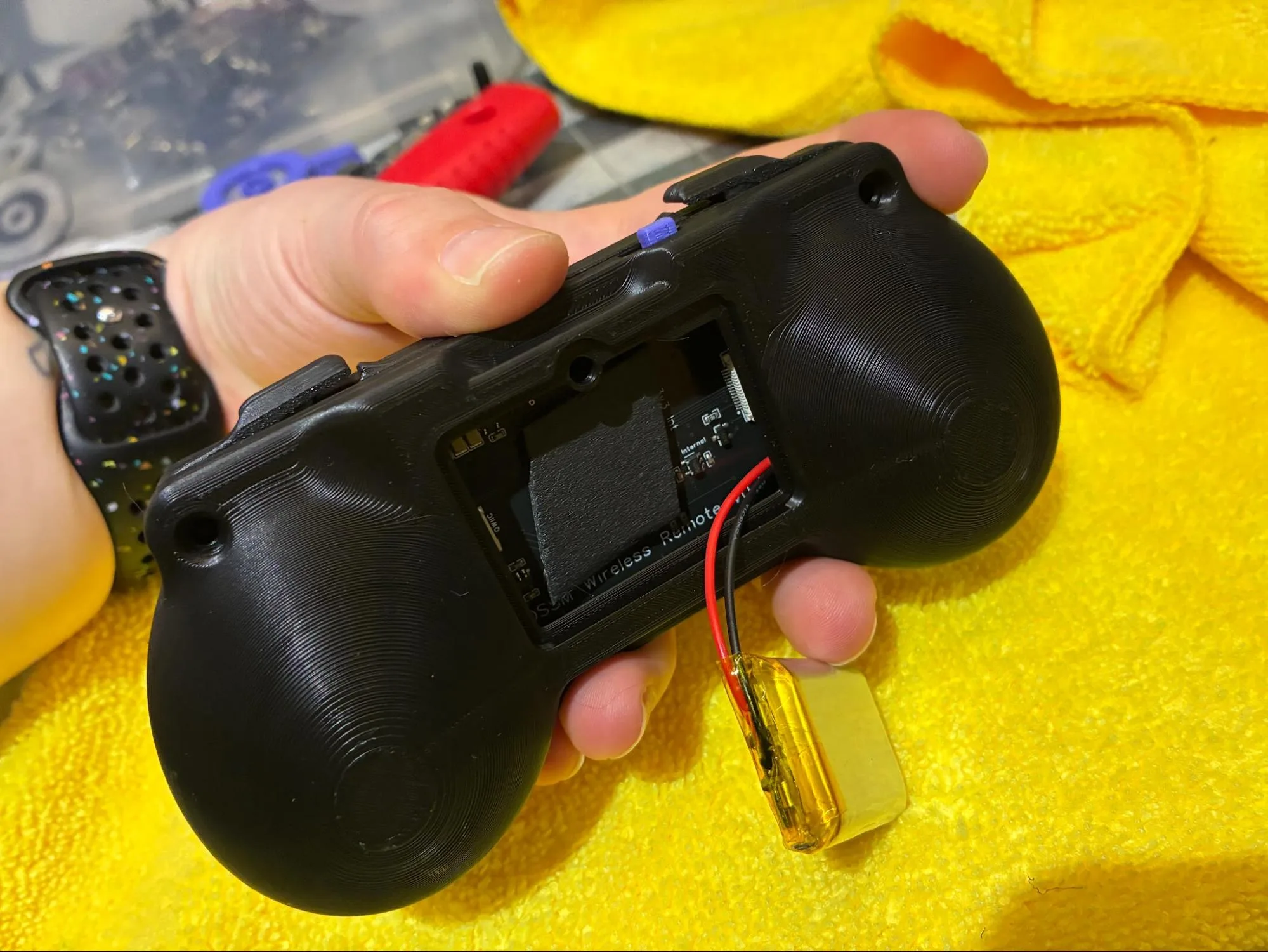
Battery routing reference. -
Using a medium torque setting, fasten the front and back housings together with tri-lobe screws.
The screw is deep enough when the screwdriver ratchets.
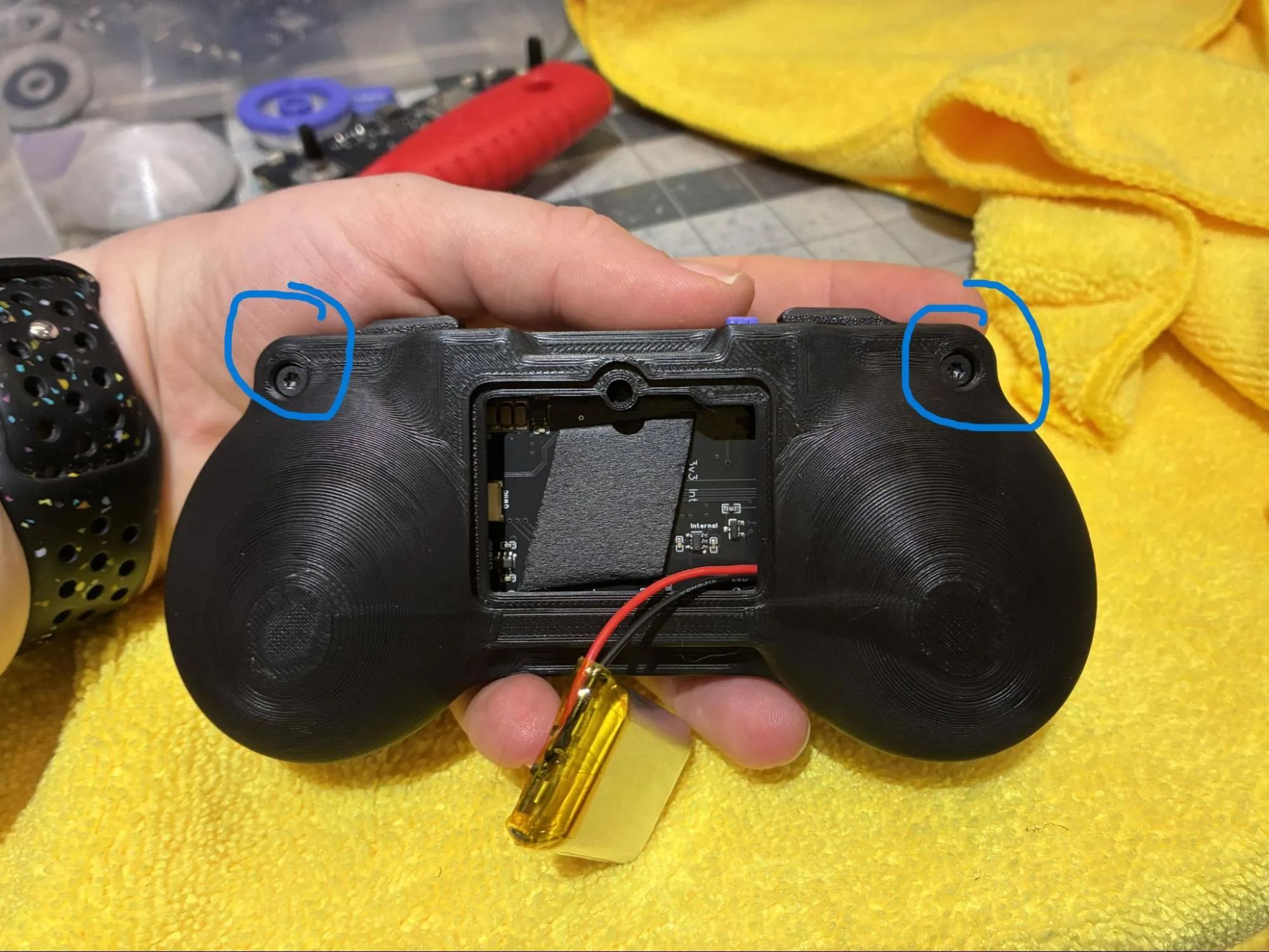
Fasten the rear housing screws. -
Fasten the front-housing screw holes with the same tri-lobe screws.
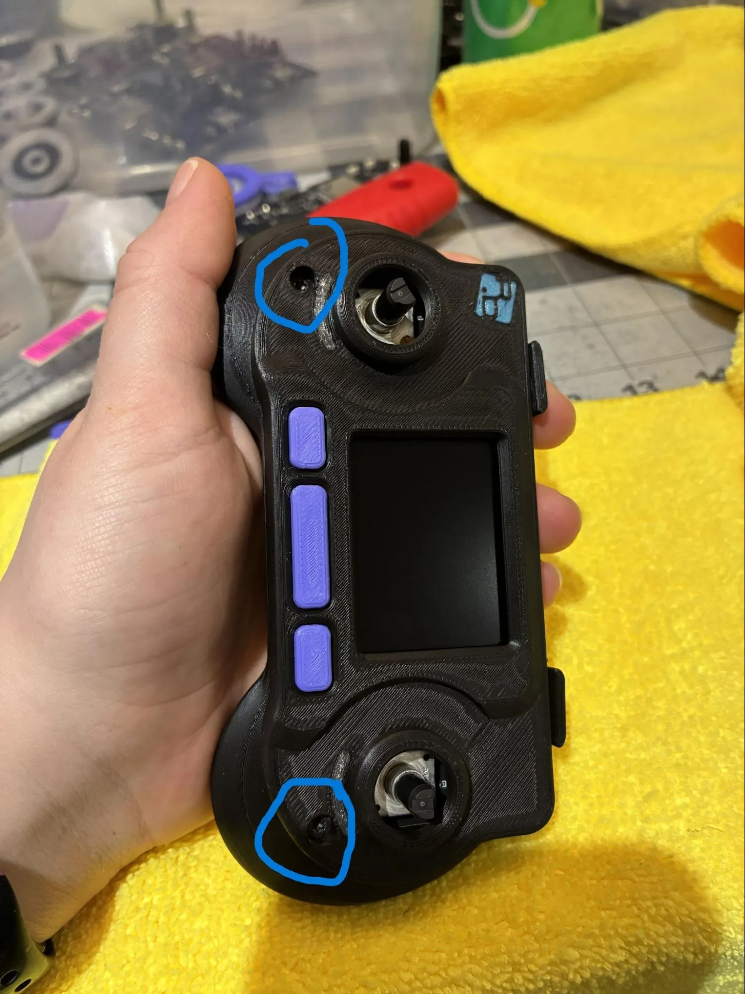
Fasten the front housing screws. -
Place the
batteryinside the battery compartment.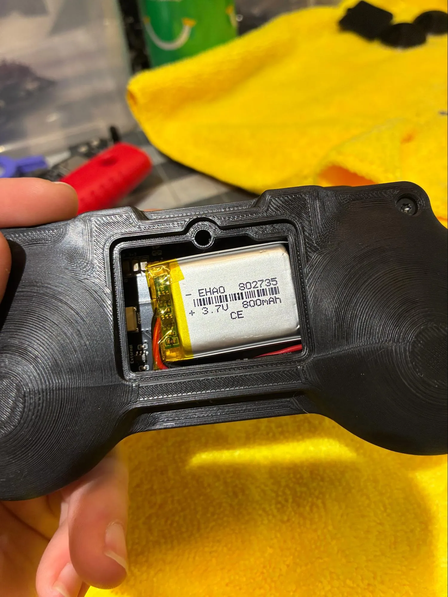
Battery placed in the compartment. -
Place the
battery-flapover the battery and screw it shut with tri-lobe screws.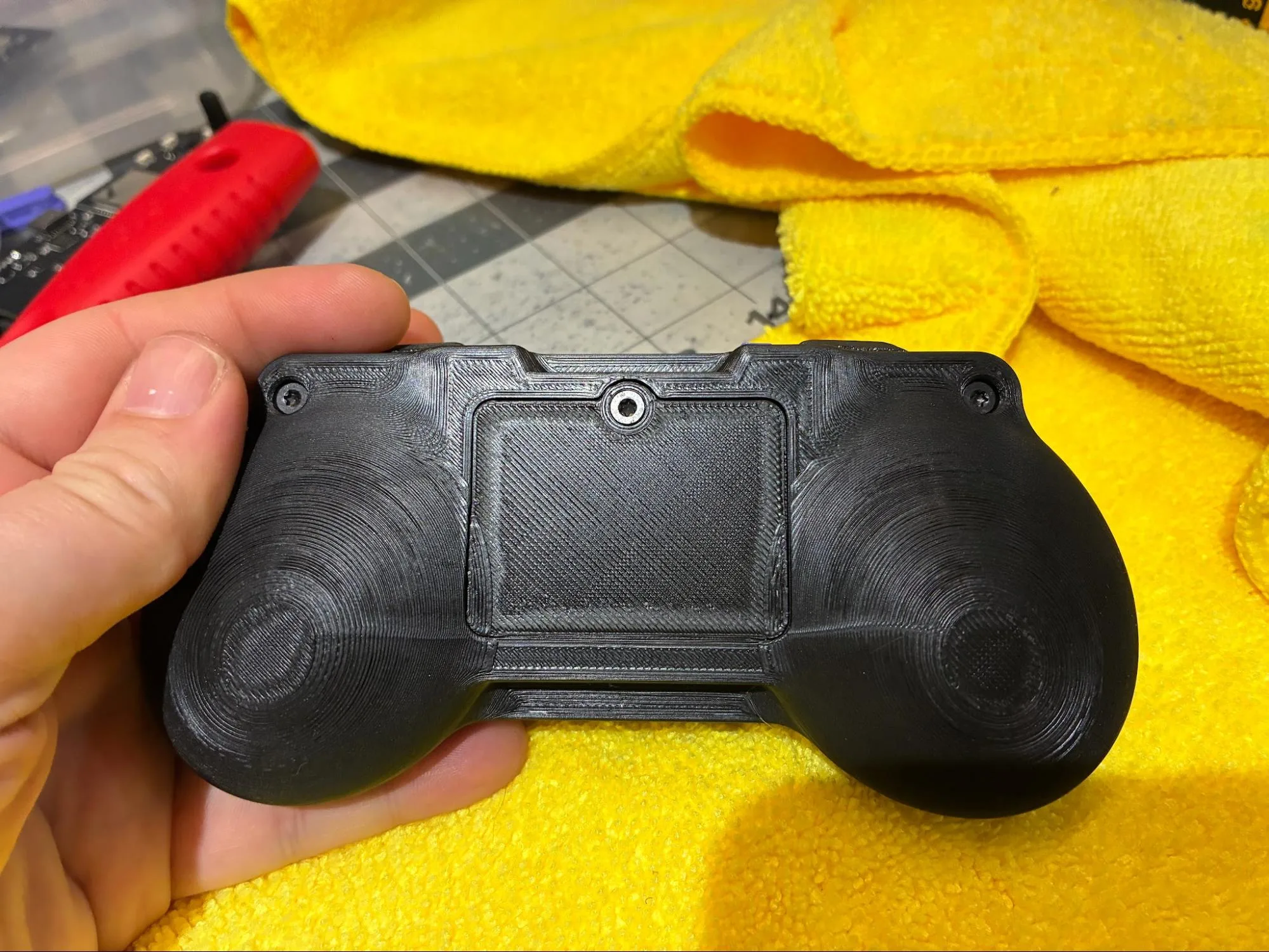
Battery cover installed. -
Confirm the housing is fully closed, all screws are seated, and the battery cover is secured before continuing.
Install Knob and Test
-
Use a small screwdriver to clean any excess filament from the interior knob circle.
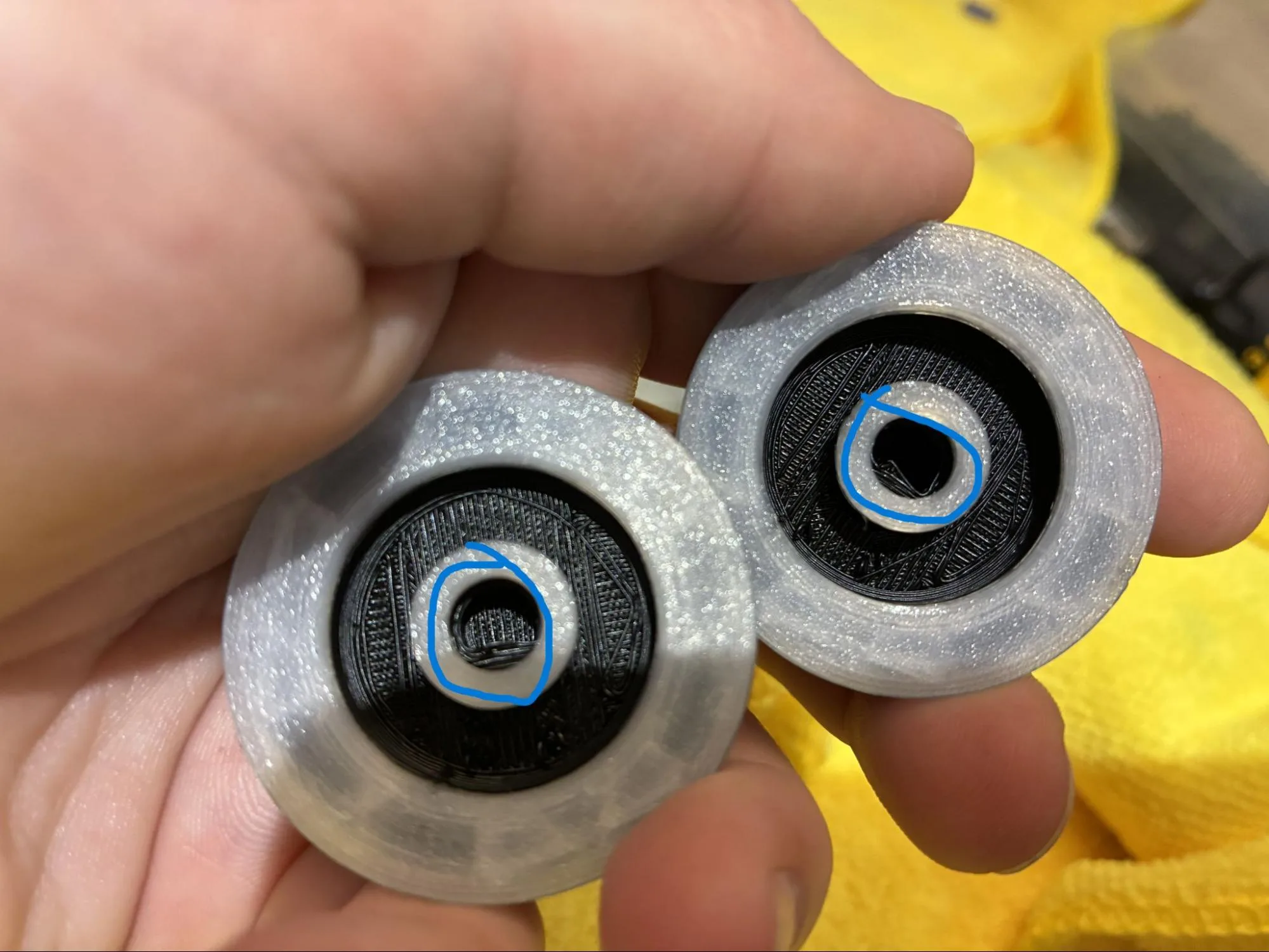
Clean the knob bore before installation. -
Align the encoder shape with the interior knob circle shape and press the
knobonto the encoder until it softly clicks.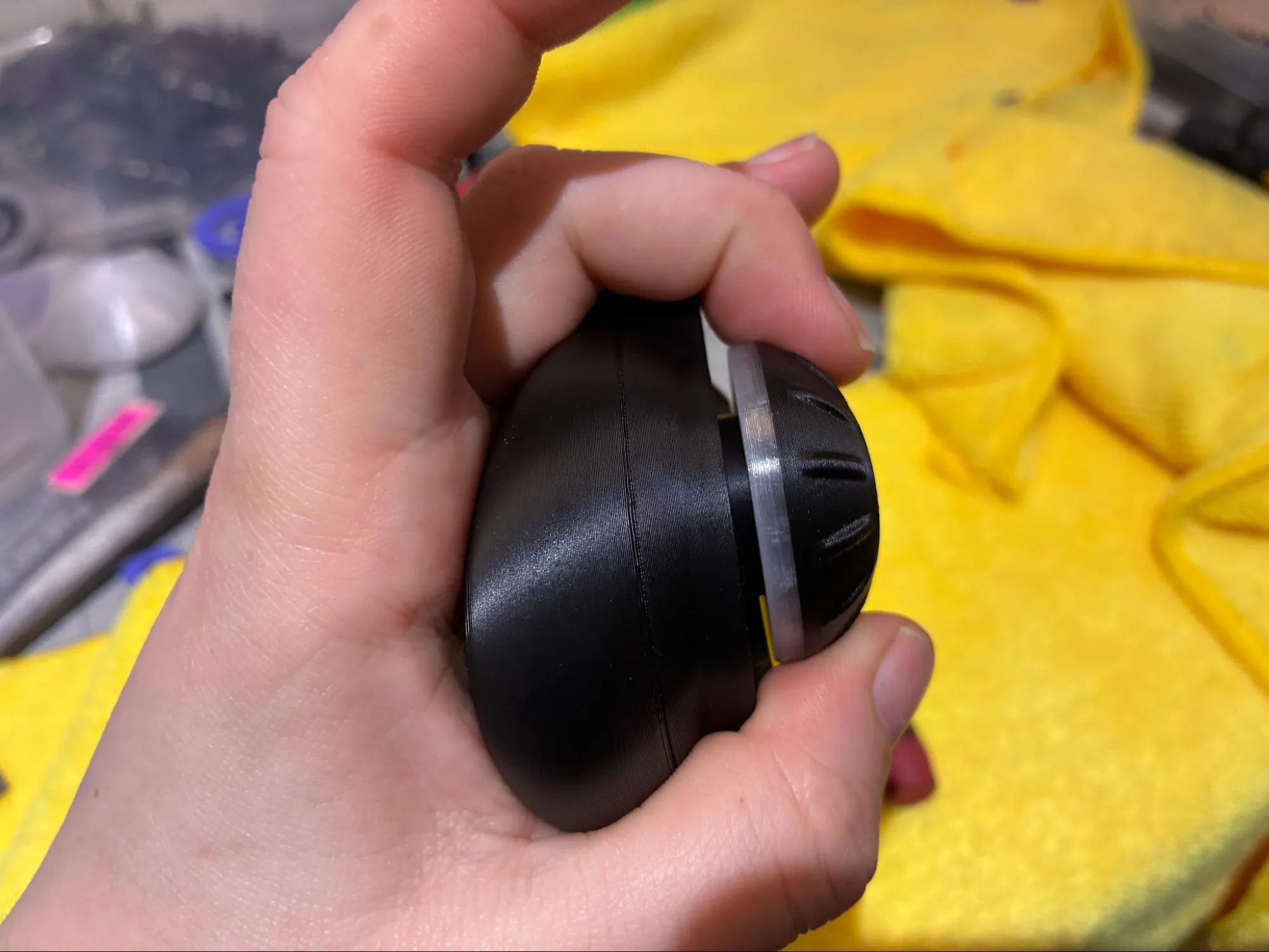
Press the knob onto the encoder. -
Turn on the device and test as per protocol.
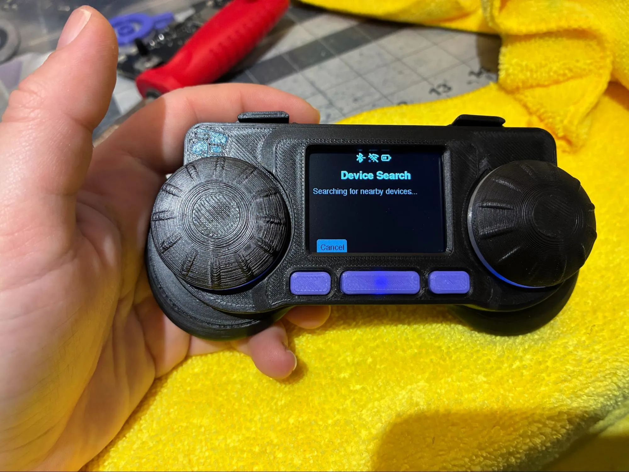
Device powered on for final test.
Final Assembly
- Confirm the PCBA edges are smooth and do not catch on the housing.
- Confirm the weather stripping is centered and adhered to the PCBA.
- Confirm the power switch cover moves the on/off switch cleanly.
- Confirm the front-housing bumpers are trimmed.
- Confirm the screen is flush and glued with a low-profile bead.
- Confirm the buttons are installed and move freely.
- Confirm the PCBA sits flush in the front housing.
- Confirm the screen ribbon is fully inserted and the connector is closed.
- Confirm the screen ribbon and battery wires are routed away from pinch points.
- Confirm the housings and battery cover are fastened with tri-lobe screws.
- Confirm the knob is seated on the encoder.
- Confirm the device powers on and passes the current functional test protocol.
QC Checklist
- PCBA edges were deburred until smooth.
- Weather-strip area was cleaned with isopropyl alcohol.
- 2.5 cm weather-strip piece was installed on the PCBA.
- Printed power switch cover was installed.
- Battery was connected with the PCBA switched off.
- Front-housing bumpers were trimmed.
- Screen film was removed.
- Screen was installed flush in the front housing.
- Screen was secured with a thin, low-profile hot glue bead.
- Buttons were dropped into the front housing.
- Screen ribbon was fed through the PCBA cutout.
- PCBA was pressed flush into the housing.
- Screen ribbon connector was opened, seated, and closed.
- Screen ribbon was tucked into the housing.
- Back housing was aligned around the on/off switch.
- Battery was pulled through the battery compartment opening.
- Front and back housings were fastened with tri-lobe screws.
- Battery was placed inside the battery compartment.
- Battery cover was installed and screwed shut.
- Knob bore was cleaned of excess filament.
- Knob was pressed onto the encoder until it clicked.
- Device was powered on and tested as per protocol.