Purpose
This work instruction documents the current Lockbox assembly process from printed parts through final mechanical assembly.
Use these instructions with the active PCB and CAD release for the build.
Required parts and consumables
-
Gather the required parts before starting assembly.
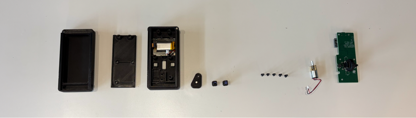
Required Lockbox assembly parts. -
Confirm the assembly set includes:
top-housingbottom-housingpcb-backinglocking-latchenter-buttonback-buttonencoder-wheelencodermotorscreenbattery- 7x
torx-screw - 4x
4mm-magnet - 4x
rubber-foot VHB-double-sided-tapehot-glueSA-glue
-
If all required parts are present, continue onward.
Tools
- Electric screwdriver or hand driver with T7 Torx bit
flat-jaw-plierstweezerspaperclipisopropyl-alcoholmicrofibre-cloth
Prepare plastic components
-
Work on a soft cloth. The front face scratches easily.
-
Check each printed part in good lighting before assembly. Look for curled corners, squished layers, large plastic blobs, blocked magnet inserts, and blocked screw holes.
-
Use a smooth PEI print bed for front-facing cosmetic parts and a textured PEI print bed for internal parts.
-
Inspect each printed part before installing electronics.
-
Confirm the plastic components are clean, correctly printed, and free of obstructions before continuing.
Part reference photos
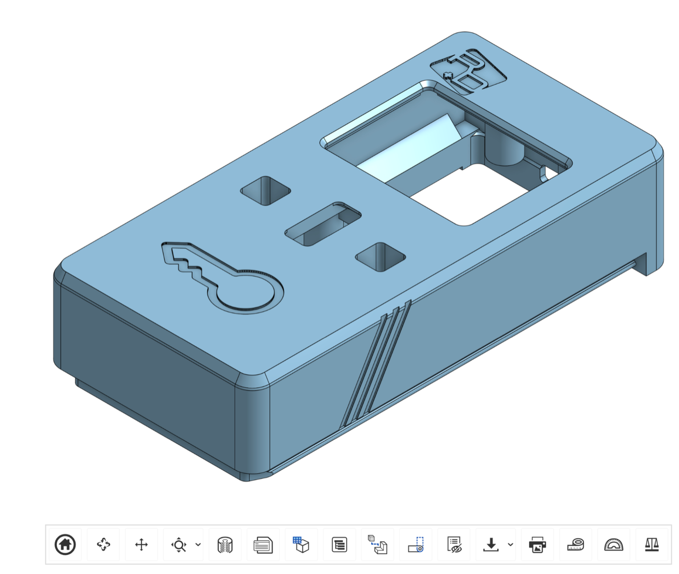
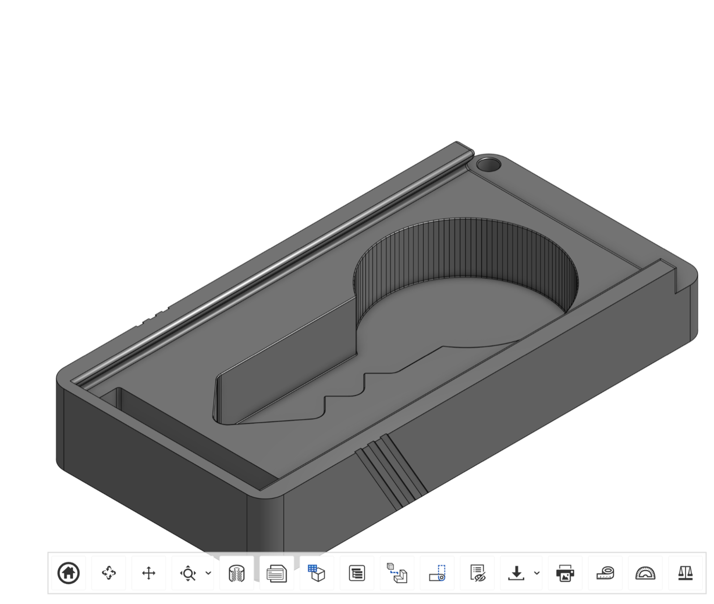
Use these photos while inspecting printed parts.
top-housing
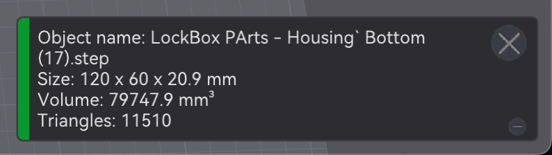
bottom-housing
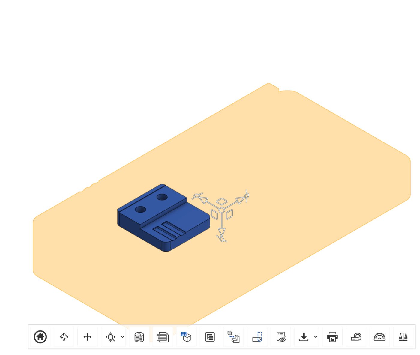
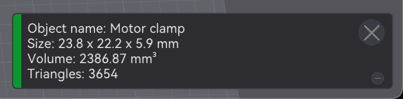
motor-clamp
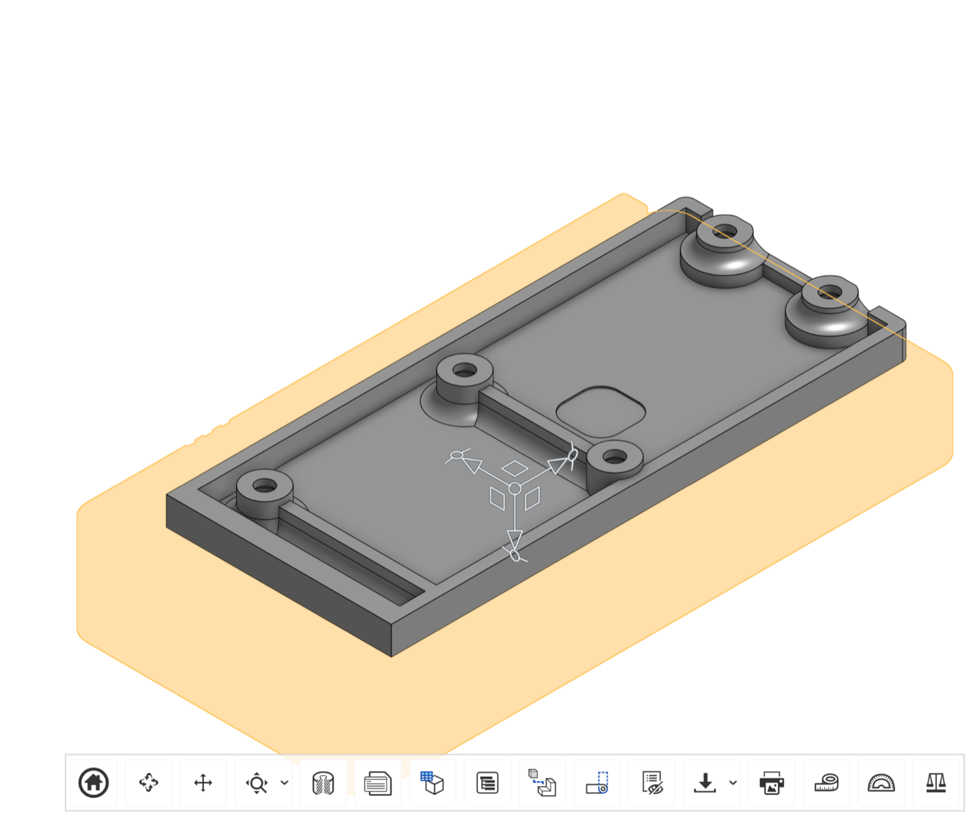
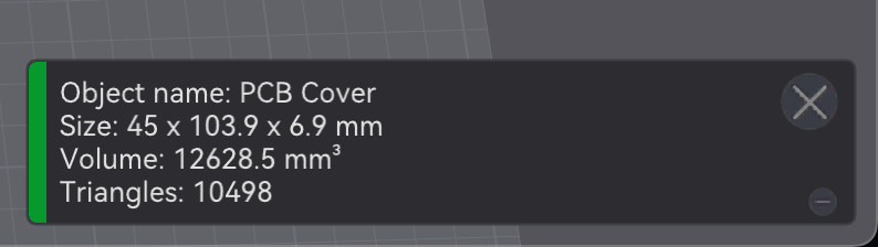
pcb-cover
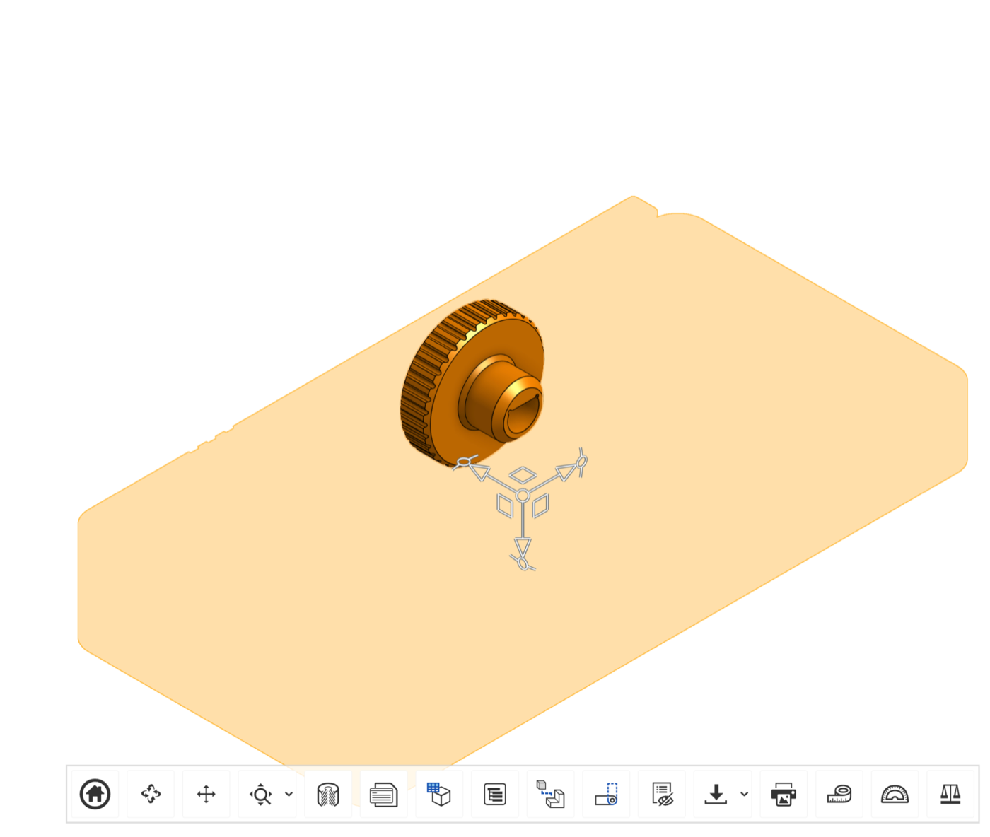
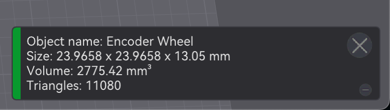
encoder-wheel
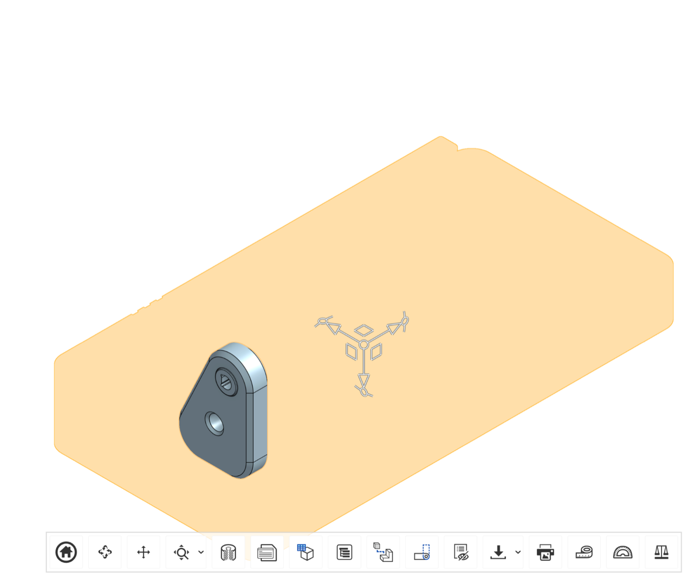
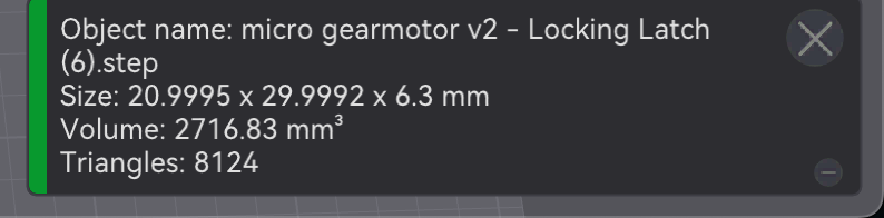
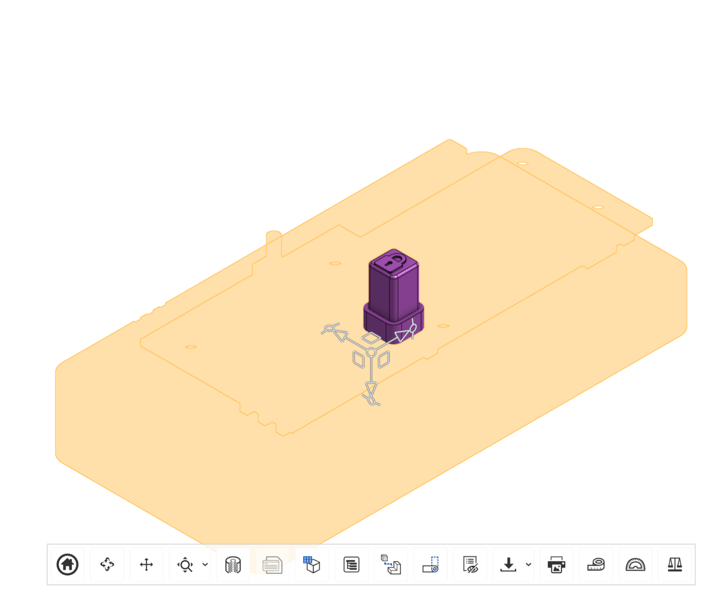
locking-latch
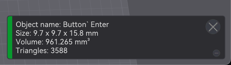
enter-button
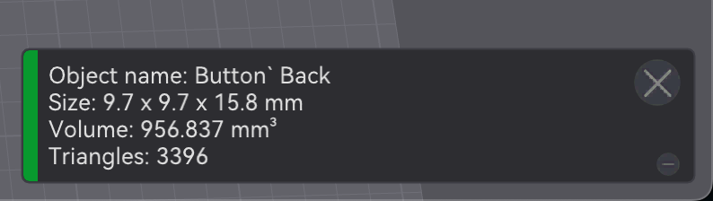
back-button

Install magnets
-
Install four magnets: one in the
locking-latch, one in thetop-housing, and two in thebottom-housing. -
Use a
paperclipto lightly coat the inside of each magnet insert withSA-glue.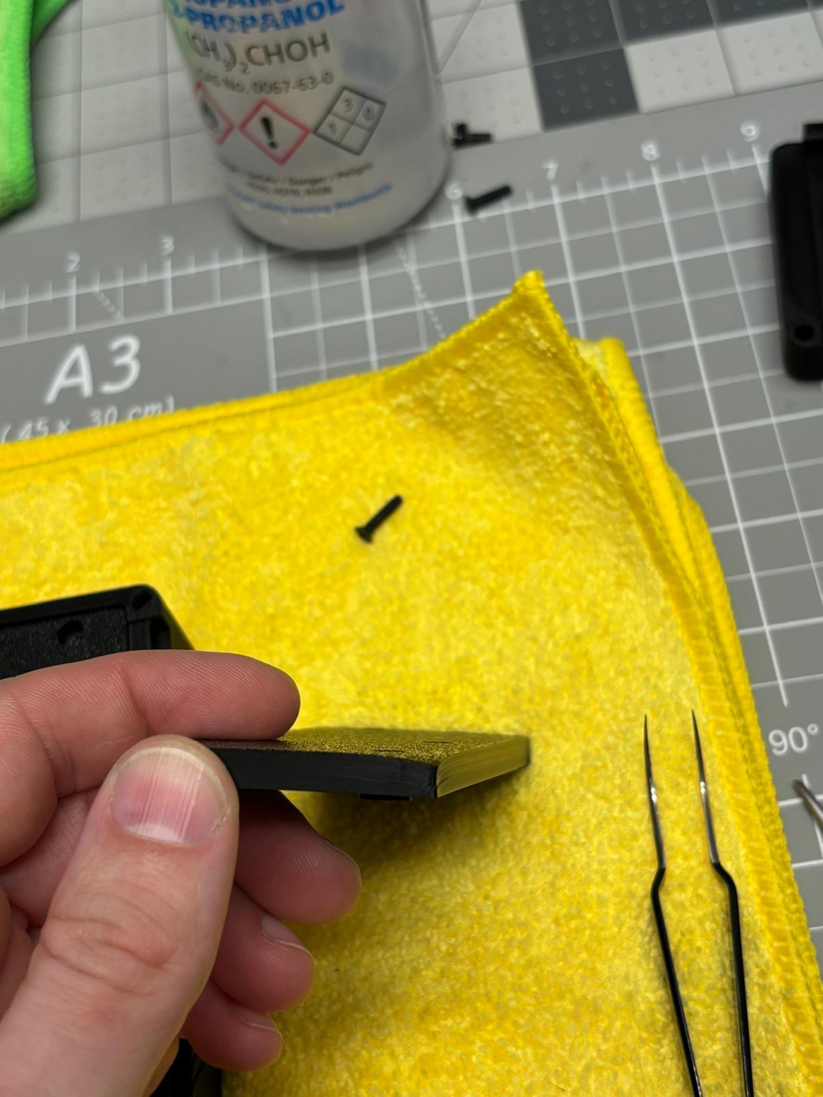
Apply a light coat of glue inside the magnet insert. -
Check magnet polarity before pressing each magnet into place:
locking-latch: north pole uptop-housingfront magnet: south side upbottom-housingfront magnet: north side upbottom-housingback magnet: south side up
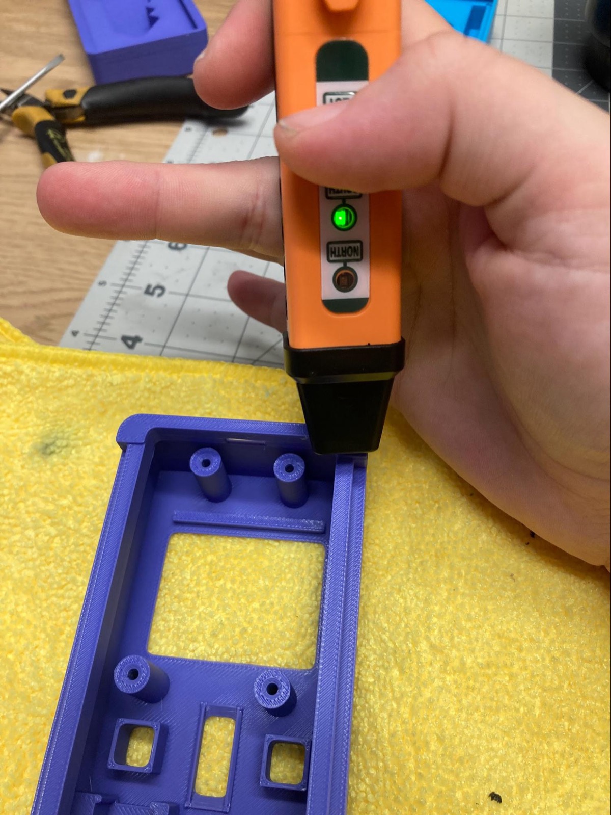
Top housing front magnet polarity. 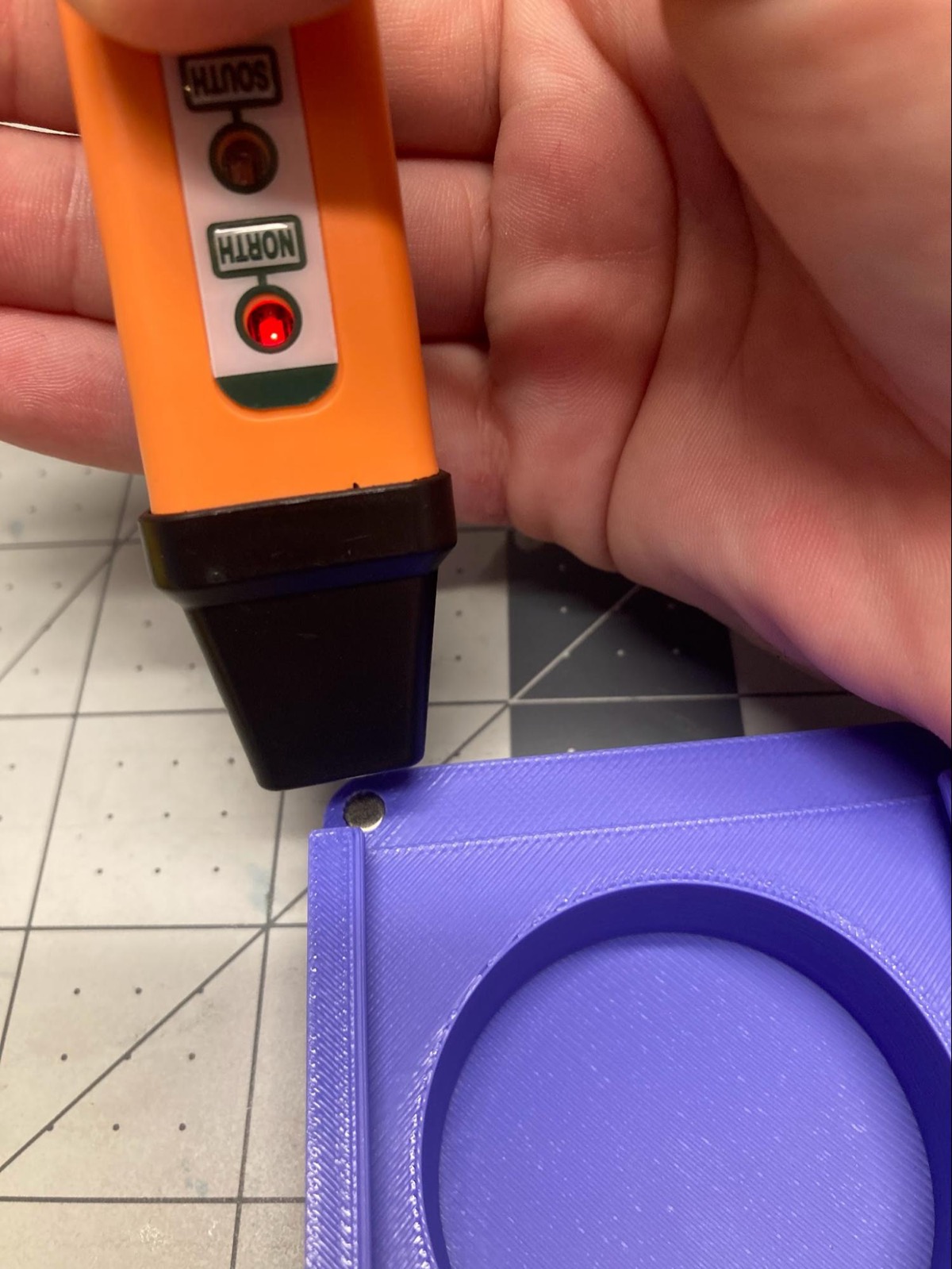
Bottom housing front magnet polarity. 
Bottom housing back magnet polarity. -
Use
flat-jaw-pliersto press magnets into their inserts. Place a foldedmicrofibre-clothbetween the pliers and the Lockbox body to protect the printed surface.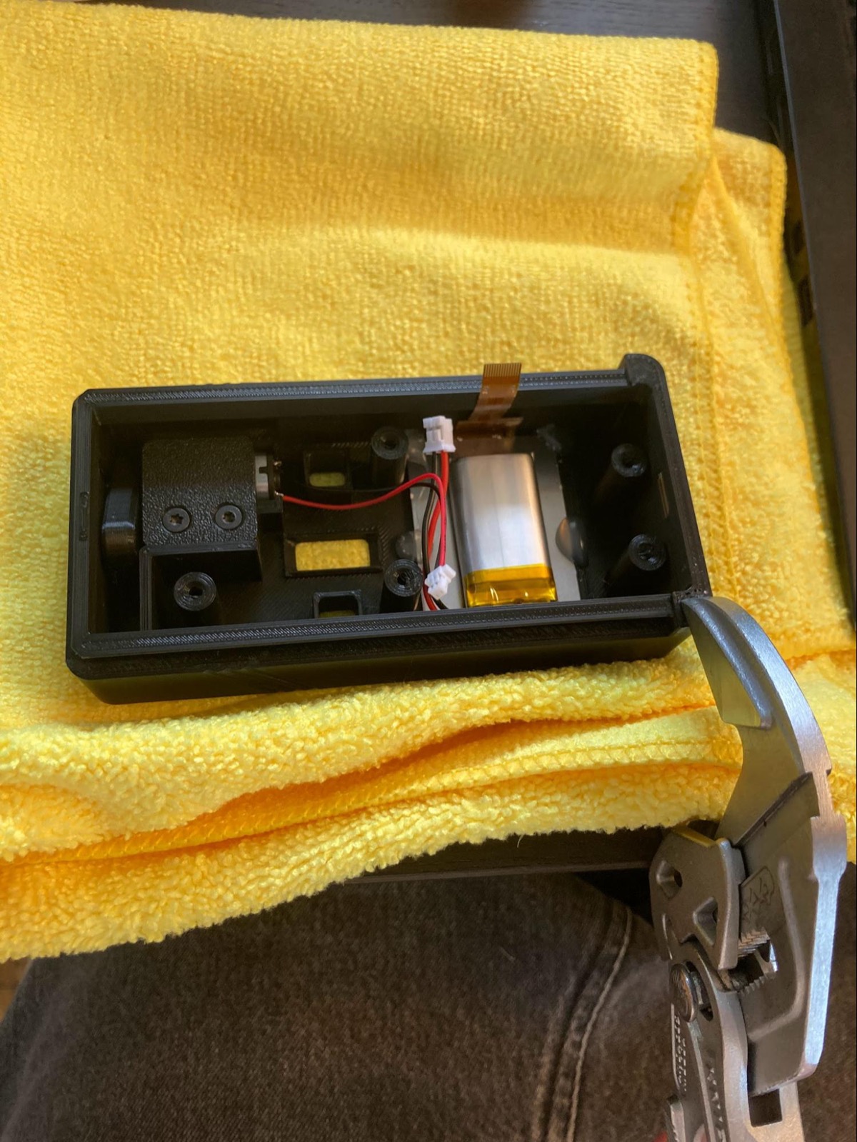
Protect the housing while pressing magnets. 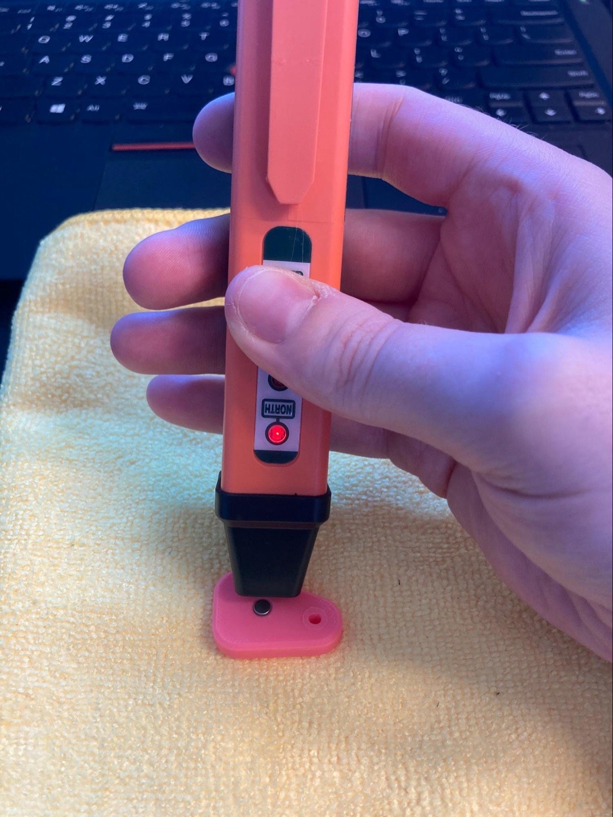
Press the lock arm magnet into place. -
Confirm each magnet is seated flush or deep enough for its insert.
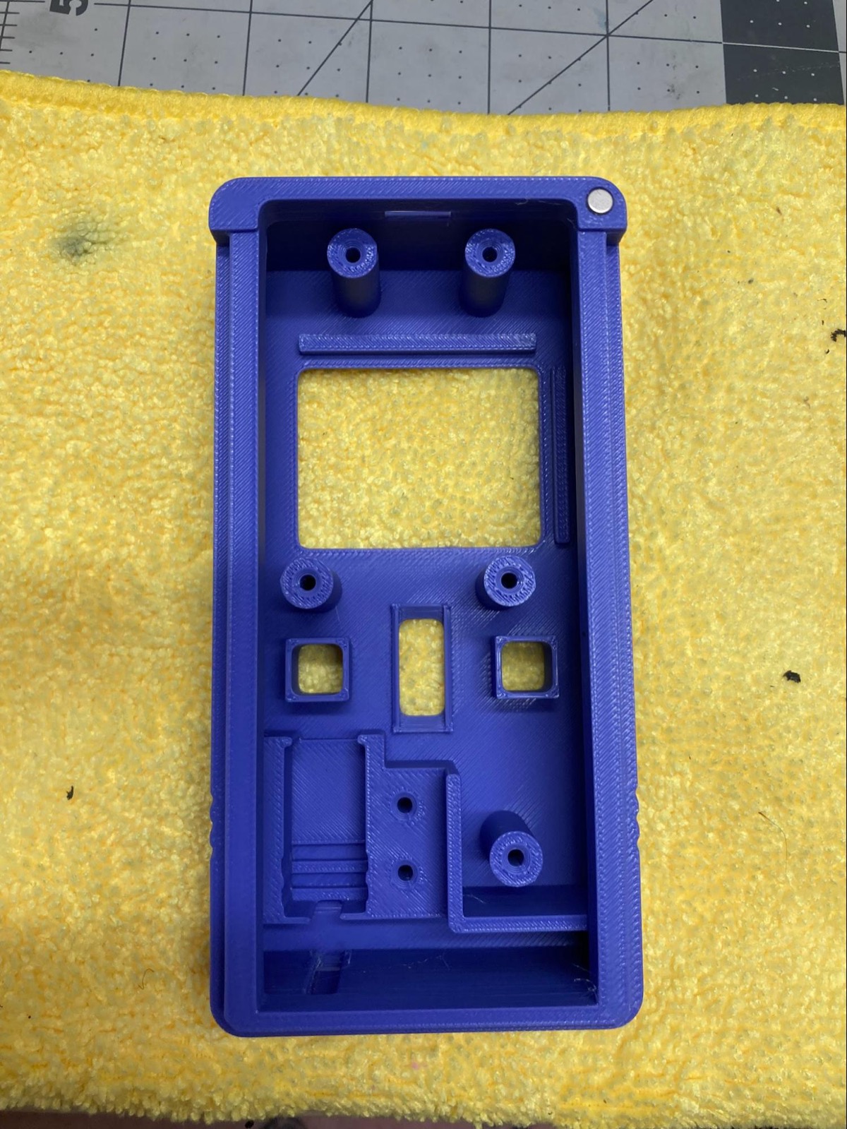
Top housing magnet installed. 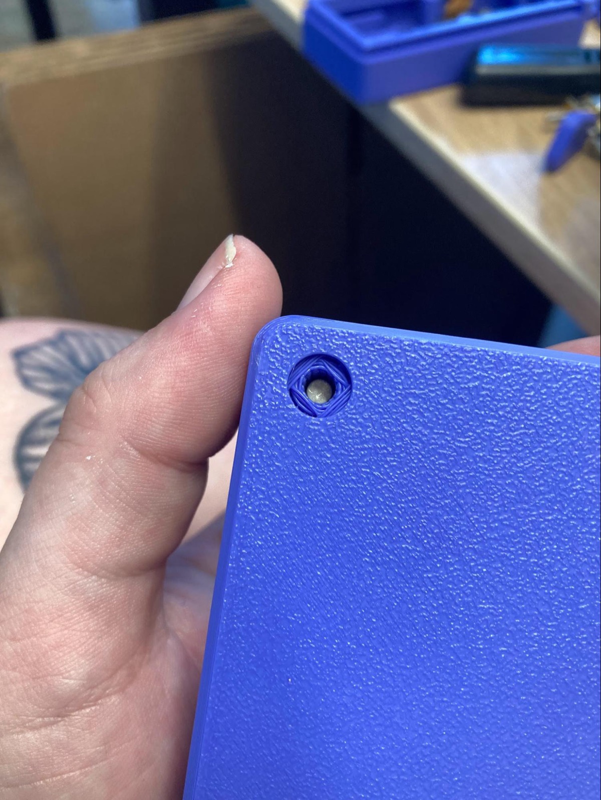
Bottom housing back magnet installed. 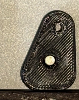
Locking latch magnet installed. -
Confirm the magnets are fully seated and glued before continuing.
Install screen and battery
-
Remove the protective film from the
screen. -
Align the
screenwith the top and right ledges of thetop-housing. -
Hold the screen in place and set it with
hot-glueat the corners and remaining edges. -
Wipe the rear of the
screenand the side of thebatterywith writing usingisopropyl-alcohol. -
Apply a 3/4 inch square piece of
VHB-double-sided-tapeto the writing side of thebattery.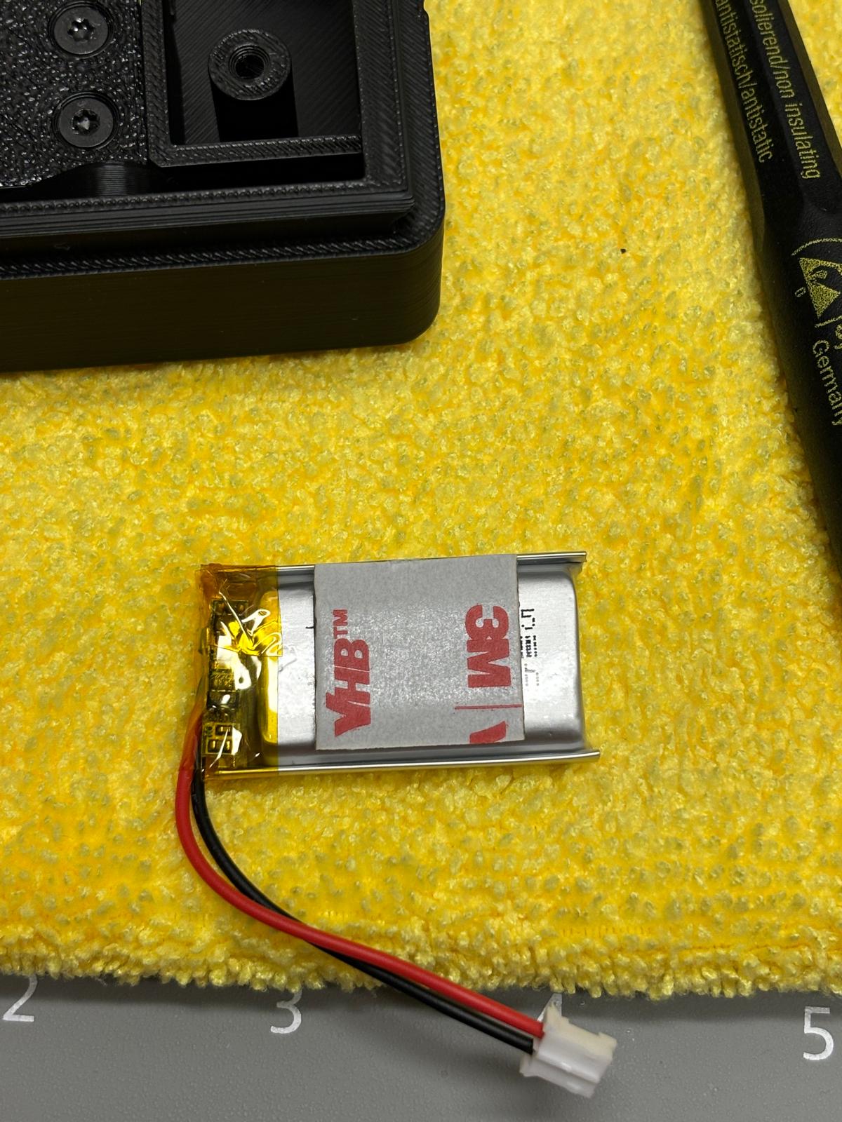
VHB tape applied to the battery. -
Place the
batteryface down on the back of thescreenwith the cables exiting toward the lower right. Set withhot-glueas needed.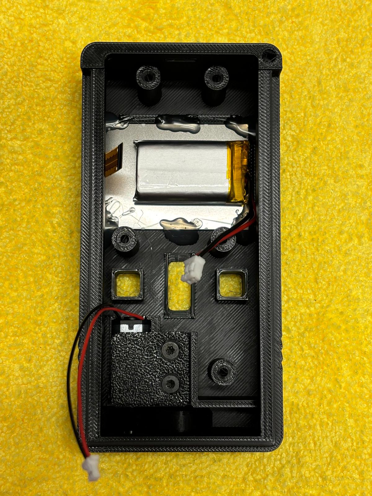
Screen and battery installed in the top housing. 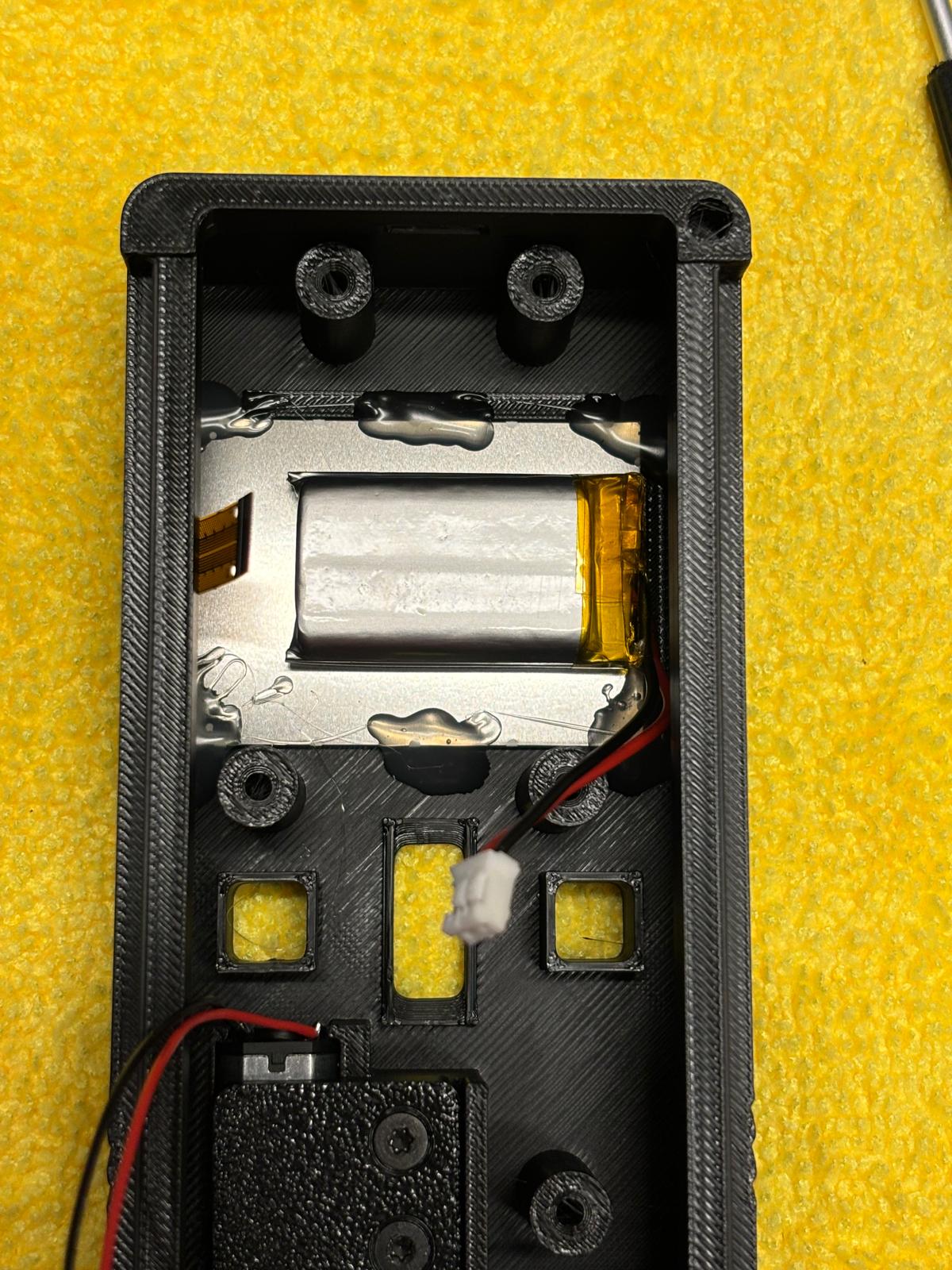
Screen, battery, and motor layout reference. -
Confirm the screen and battery are secure and that wires remain accessible.
Install encoder
-
Test-fit the
encoder-wheelbefore soldering or gluing. -
Apply
SA-glueto the flat face of the encoder shaft. -
Line up the flat of the encoder shaft with the flat face inside the
encoder-wheel, then install the wheel. -
Solder the
encoderonto the PCB. Make sure the encoder is fully seated so the wheel stays straight.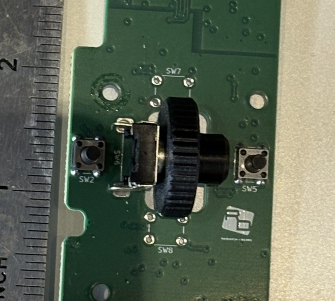
Encoder installed on PCB. 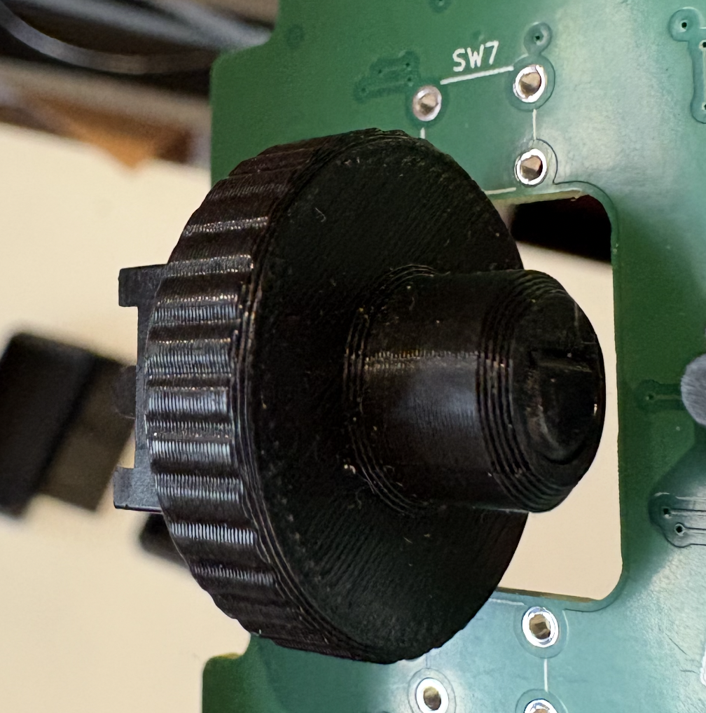
Encoder wheel installed. -
Confirm the encoder wheel rotates freely before continuing.
Install motor
-
Check motor polarity before installing the motor assembly.
-
If soldering the motor lead during this build, cut the motor connector lead length to 7 cm before final routing.
-
Place the
locking-latchon themotor. Do not glue the latch to the motor.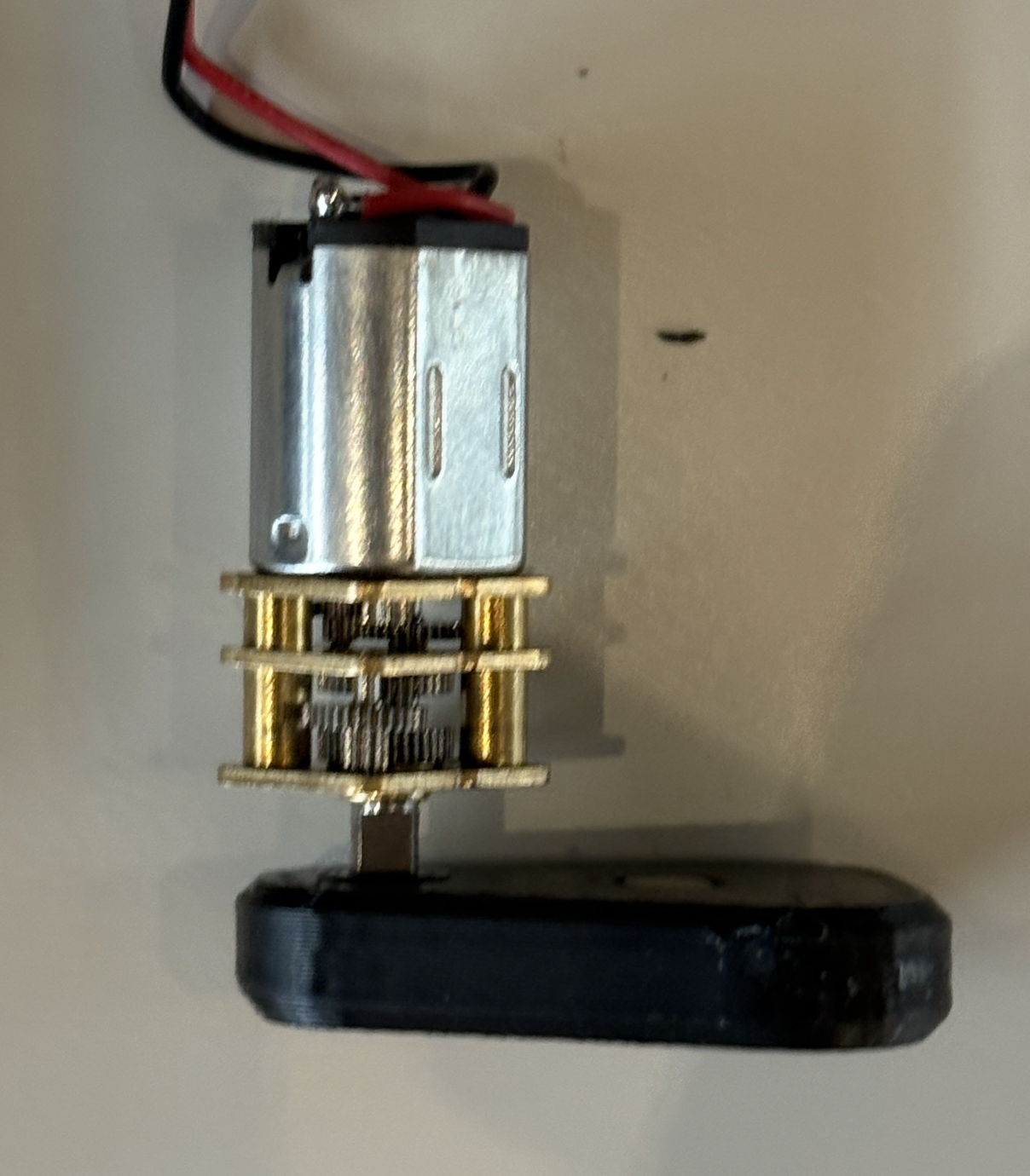
Locking latch placed on the motor. -
Slide the latch onto the motor assembly about halfway, then place the
motorin thetop-housing.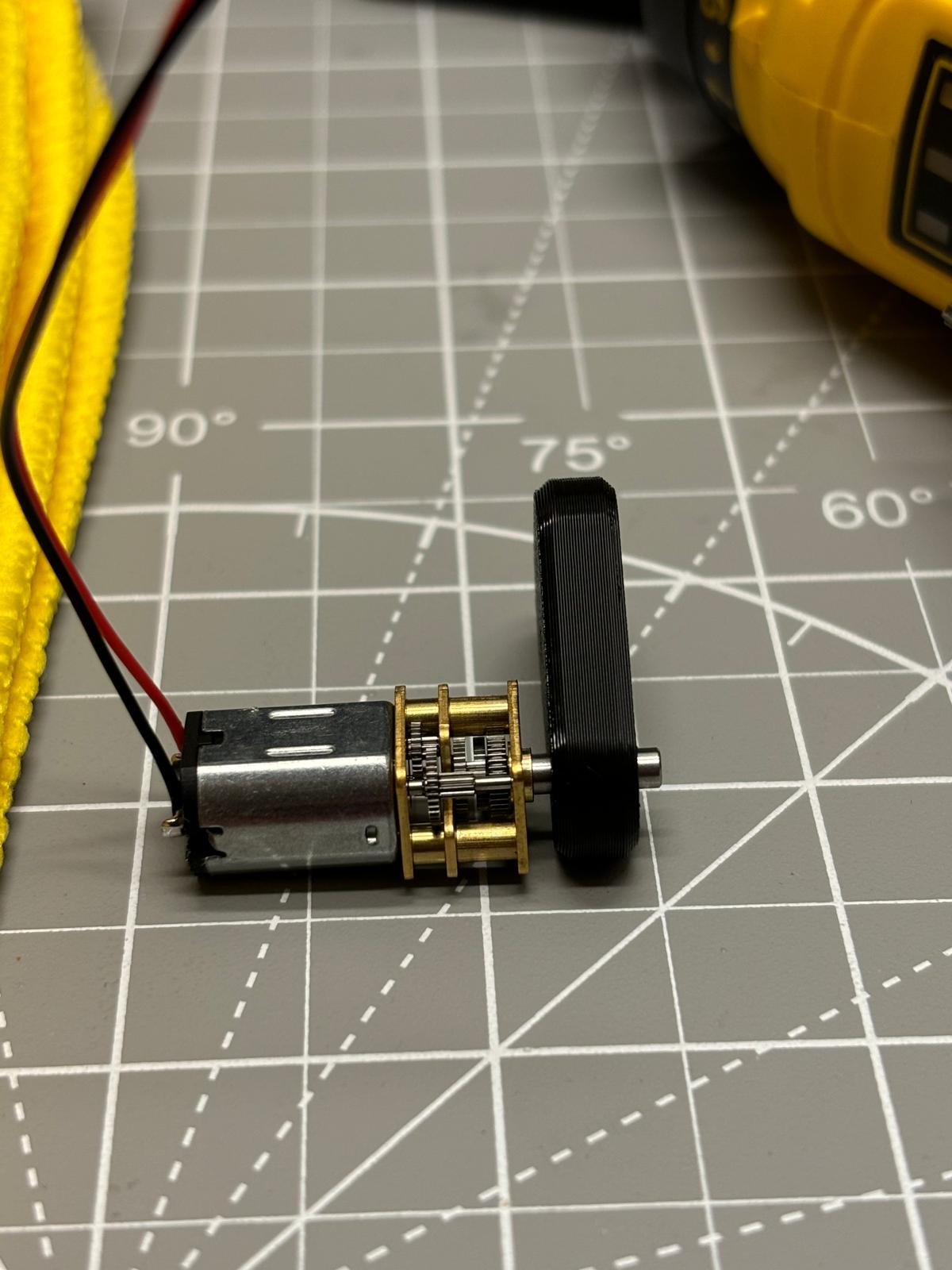
Latch installed about halfway on motor. 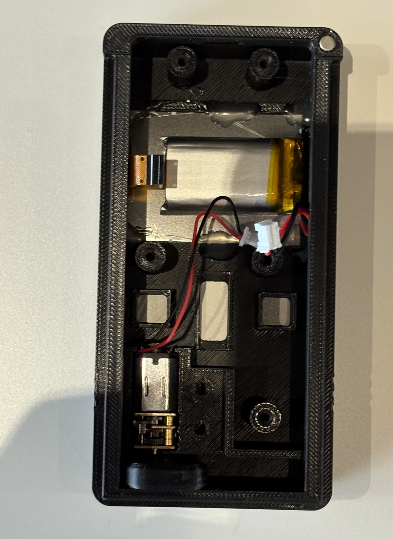
Motor placed in housing. -
Place the
motor-clampover the motor and secure it with 2xtorx-screw.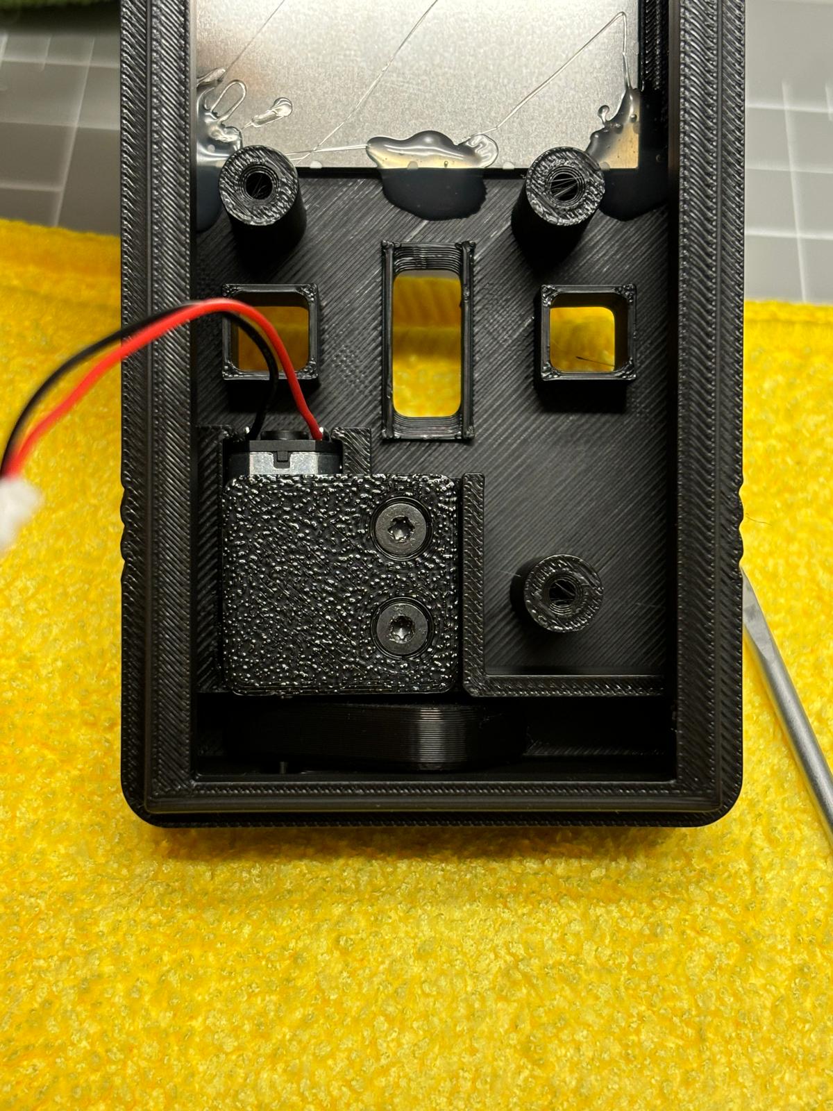
Motor clamp installed. -
Confirm the motor is seated and the latch can move without obstruction.
Install buttons and PCB
-
Place the
enter-buttonandback-buttoninto the button holes.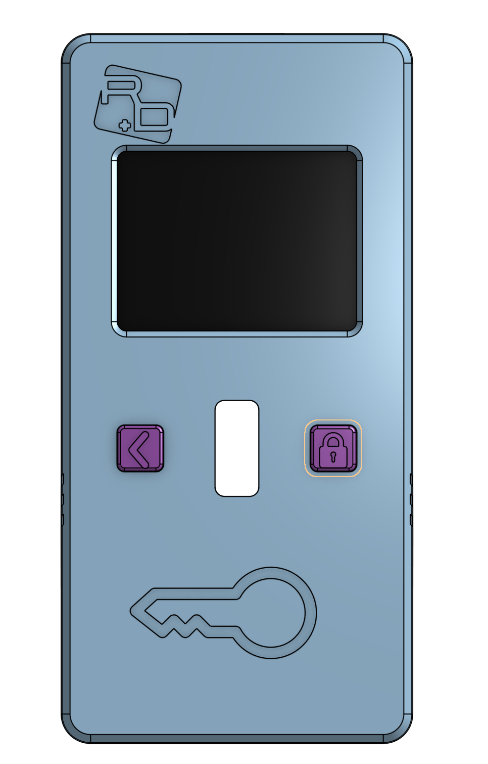
Buttons placed in housing. -
Place the
back-buttonon the left and the lock/enter button on the right. -
If the buttons are not already populated, solder the buttons onto the bottom of the PCB, the side with no other components.
-
Place the PCB onto the buttons so the
encoder-wheelpasses through the front hole.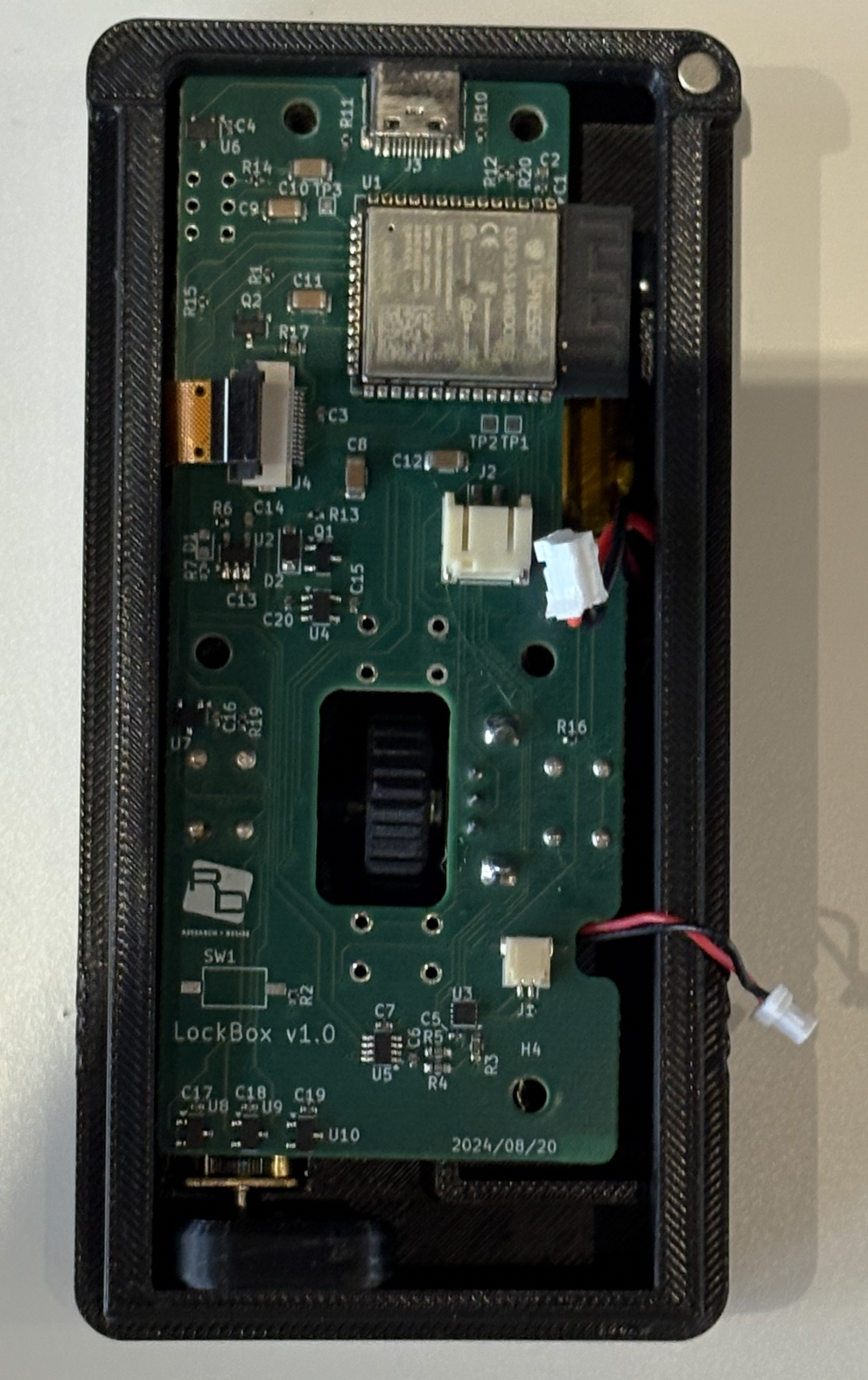
PCB placement over buttons. -
Do not cover the
screen-ribbon-wire,battery-wire, ormotor-wire.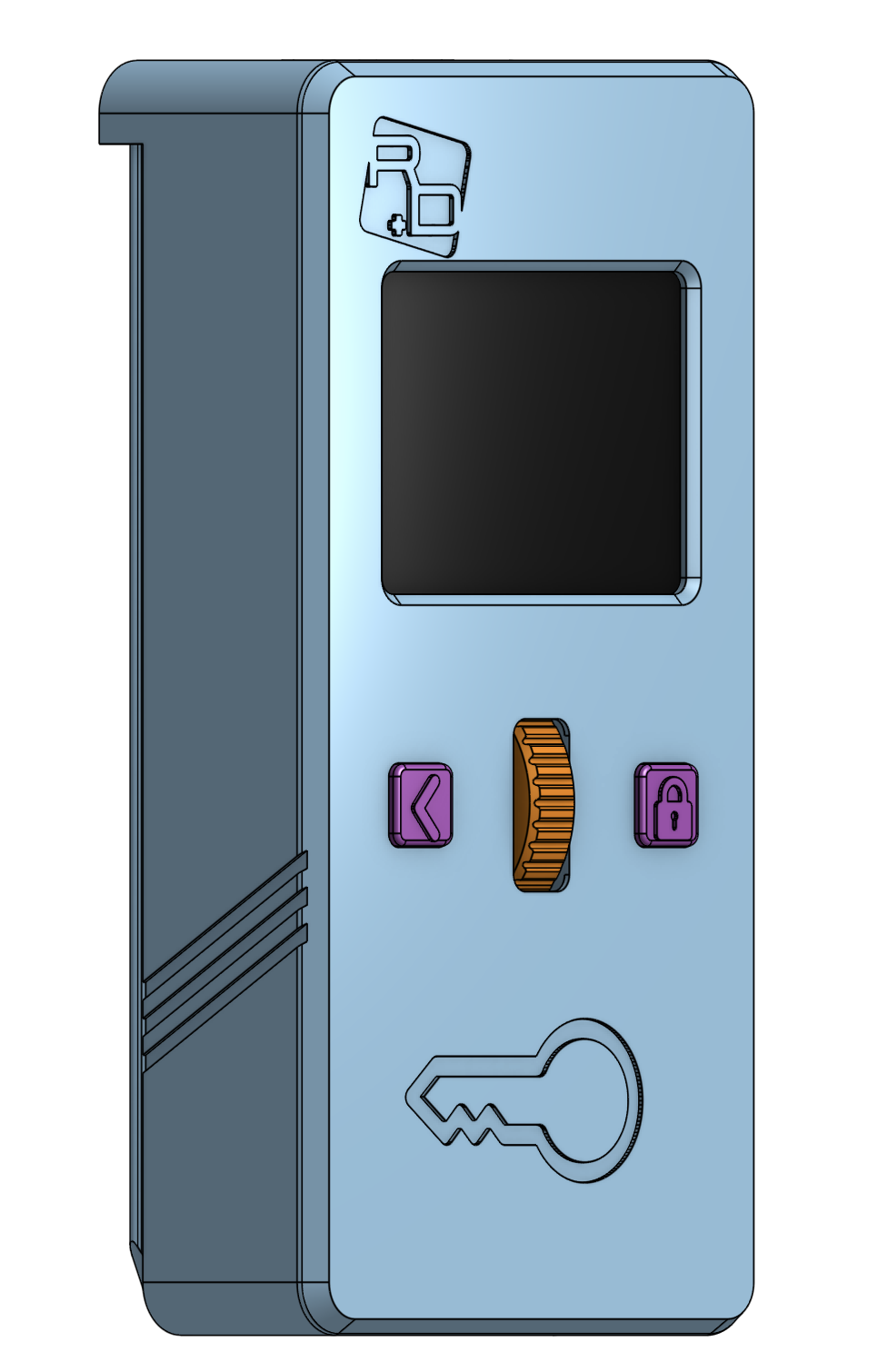
PCB seated in housing. -
Confirm the buttons actuate correctly and the encoder wheel is centered in the opening.
Connect cables
-
Open the screen ribbon connector latch.
-
Insert the
screen-ribbon-wire, then close the latch. The lower white bar should not be visible after the latch is closed. -
Plug the
battery-wireandmotor-wireinto the PCB. -
Route the motor wires left and over the PCB.
-
Keep the battery cable away from the mounting hole below it so the cable does not get pinched by the cover.
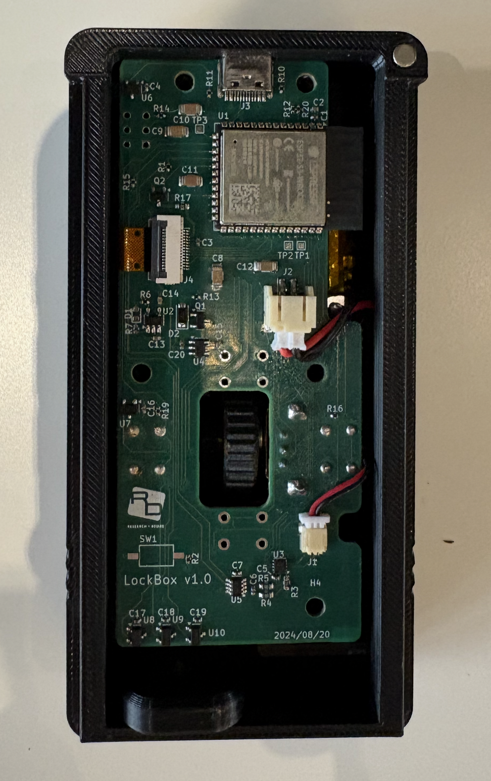
Screen, battery, and motor cables connected. 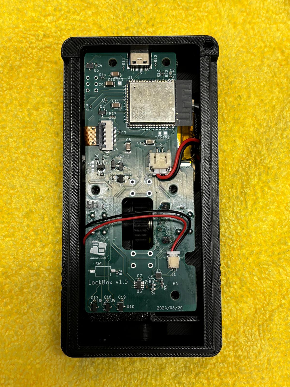
PCB cable routing reference. -
Confirm each cable is fully seated before continuing.
Install PCB cover
-
Place the
pcb-coverover the PCB.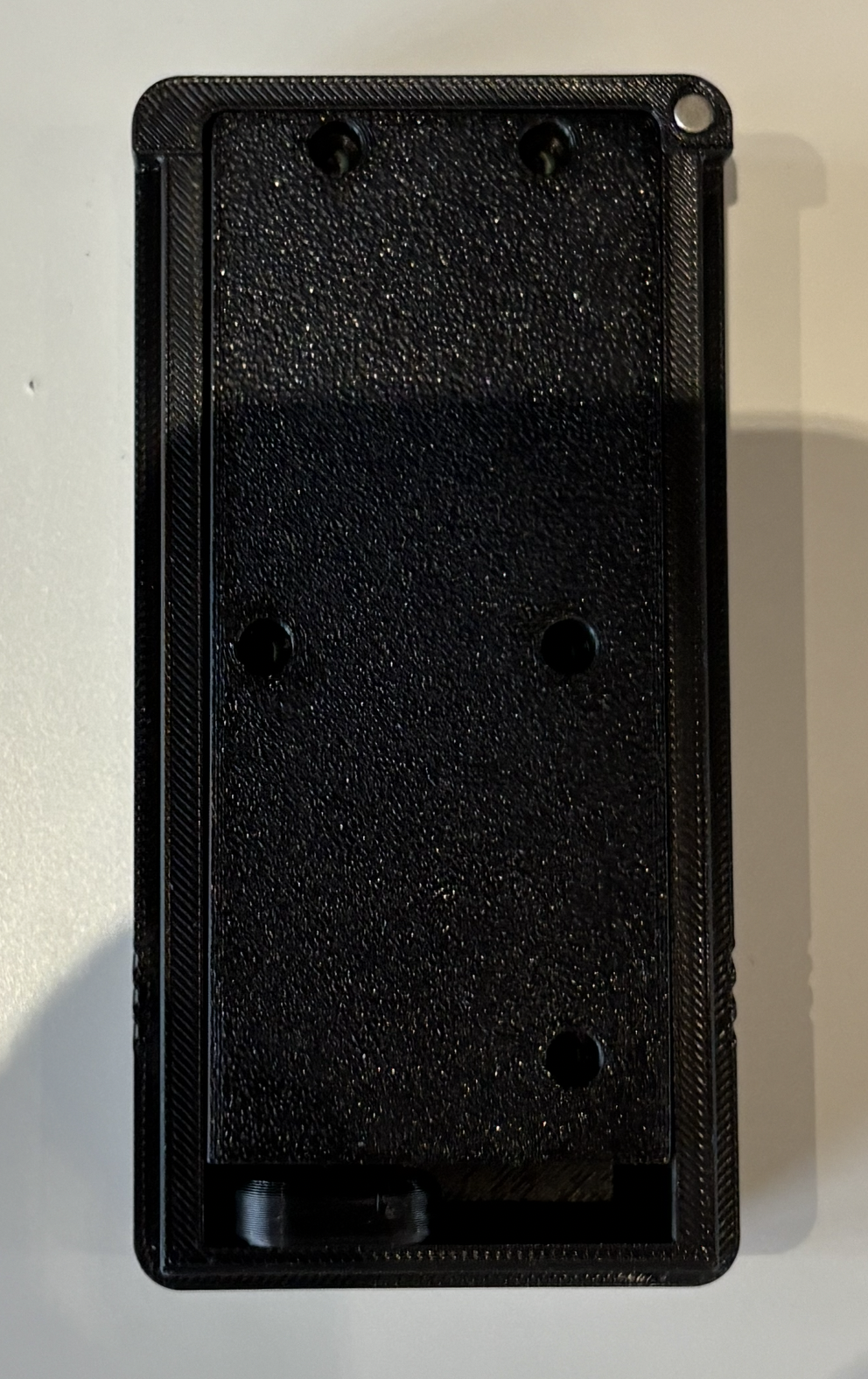
PCB cover placement. -
Secure the cover with 5x
torx-screw.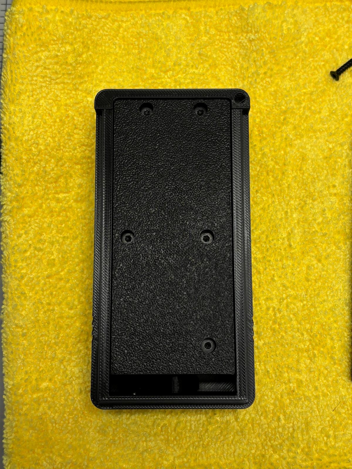
PCB cover installed. -
Confirm no wires are pinched under the cover.
Install rubber feet
-
Glue 4x
rubber-footonto the backplate.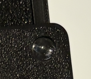
Rubber foot closeup. 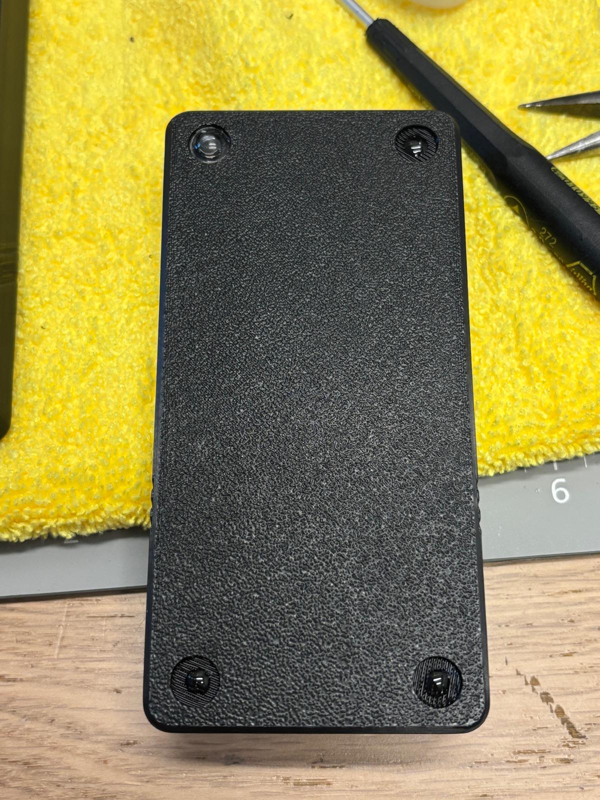
Rubber feet installed on backplate. -
Confirm all four feet are present and secure.
Final assembly
-
Slide the backplate onto the main housing.
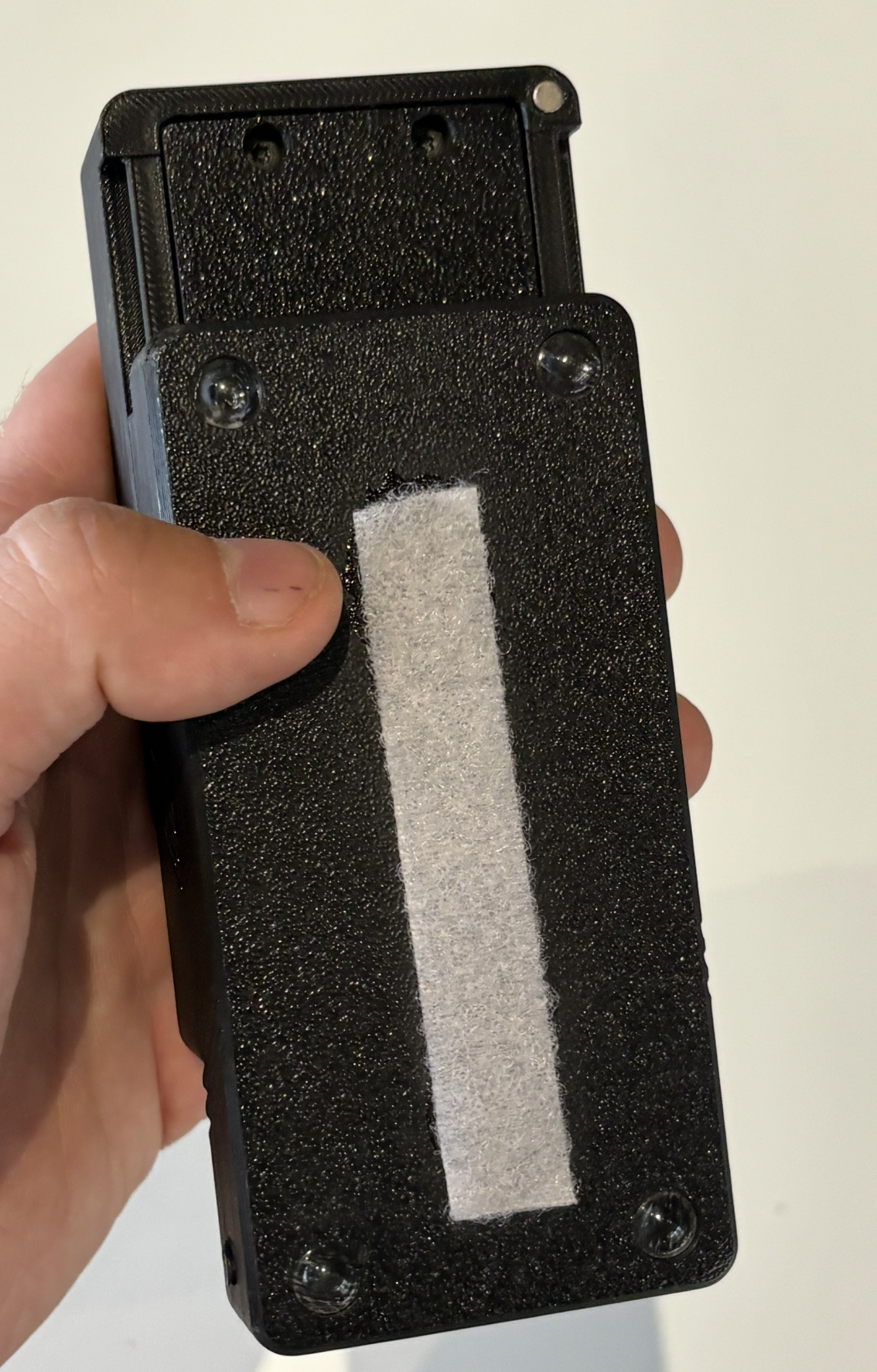
Backplate sliding onto housing. 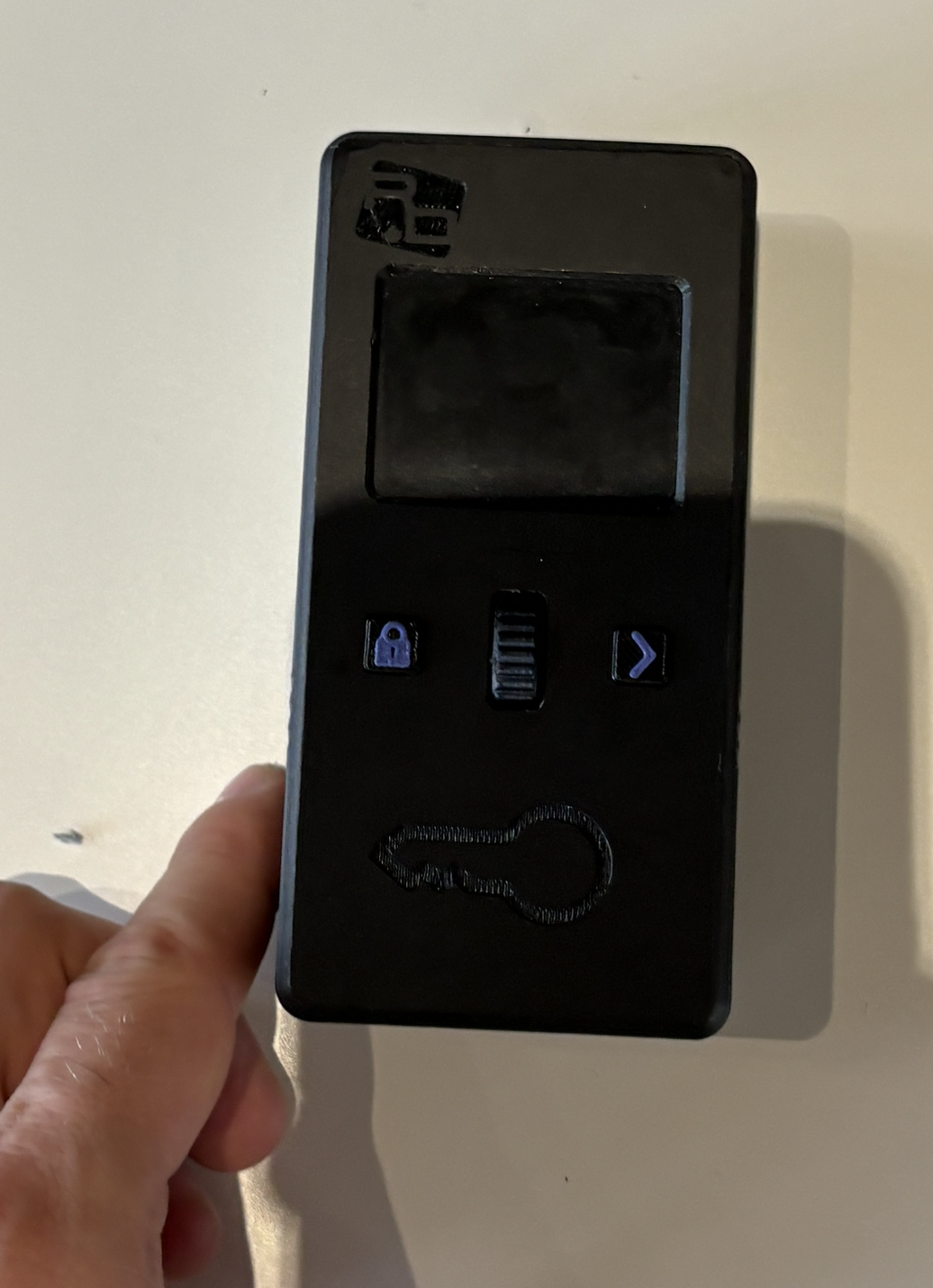
Final Lockbox assembly. -
Assembly is complete. Continue to functional testing.
QC checklist
- Confirm all required parts were present before assembly.
- Confirm printed parts are free of curled corners, squished layers, large blobs, blocked magnet inserts, and blocked screw holes.
- Confirm magnets are installed in the
top-housing,bottom-housing, andlocking-latch. - Confirm all 4 magnets are installed with the documented polarity.
- Confirm the
screenandbatteryare secured withhot-glue. - Confirm the
screen-ribbon-wireis latched and the lower white bar is not visible. - Confirm the
encoderis soldered and theencoder-wheelrotates freely. - Confirm the
locking-latchis placed on themotorwithout glue. - Confirm motor polarity and, if built by hand, the 7 cm motor connector lead length.
- Confirm the
motor-clampis secured with 2xtorx-screw. - Confirm the motor clamp is straight.
- Confirm the PCB is seated without covering the
screen-ribbon-wire,battery-wire, ormotor-wire. - Confirm the
screen-ribbon-wire,battery-wire, andmotor-wireare connected. - Confirm the buttons click cleanly.
- Confirm the encoder wheel is aligned in the front cutout and spins freely.
- Confirm the
pcb-coveris secured with 5xtorx-screw. - Confirm 4x
rubber-footare installed on the backplate. - Confirm the backplate slides onto the main housing.