Motor Control Harness
This harness connects the six-position TB1 terminal block to the four-position J12 connector, with separate ground and 24V power leads. TB1 pins 1–4 carry the DIR−, DIR+, PU−, and PU+ control signals to the matching pins on J12. Pins 5 and 6 connect to the black ground ferrule and red 24V ferrule.
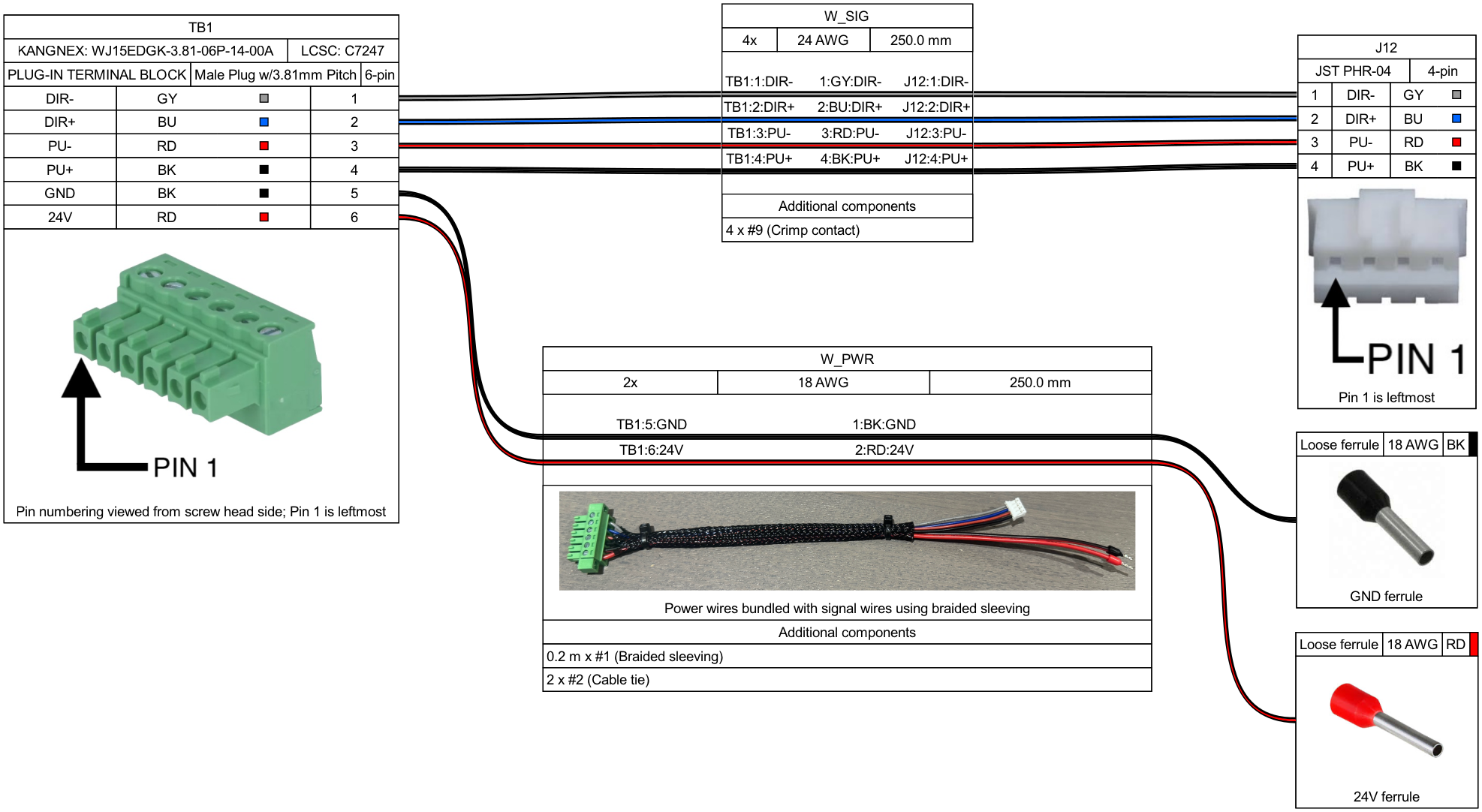
Read TB1 from the screw-head side, with the wires exiting away from you: pin 1 is on the left. The connector photos in the diagram mark pin 1 on both TB1 and J12 so you can check their orientation before wiring.
Wire with the power off
Make every TB1, J12, and ferrule connection while the 24 V power supply is unplugged from the wall. Before you plug it back in, check each connection against the diagram and make sure the red 24V and black GND ferrules are fully seated with no stray strands. Keep clear of the rail when power comes on: the OSSM starts homing automatically.
The signal wires are 24 AWG and the power wires are 18 AWG, all 250 mm long. Braided sleeving holds the middle of the harness together, leaving the J12 connector and power ferrules on separate branches.