Purpose
Assemble the Deepthroat Trainer 2026 updated all-in-one case build from the prepared PCB, housing, screen, sensor, battery, cable harness, velcro, and screws.
Required Parts and Consumables
- DTT PCB
- DTT loop velcro
- 3D printed DTT housing
- Screen
- Sensor
- Battery
- Cable harness
- 4x
0408LTFBscrews - Hot glue
Tools
- Hot glue gun
- T8 screwdriver bit
- Electric screwdriver or similar
- Torch
Prepare Components
-
Confirm the full kit is present.
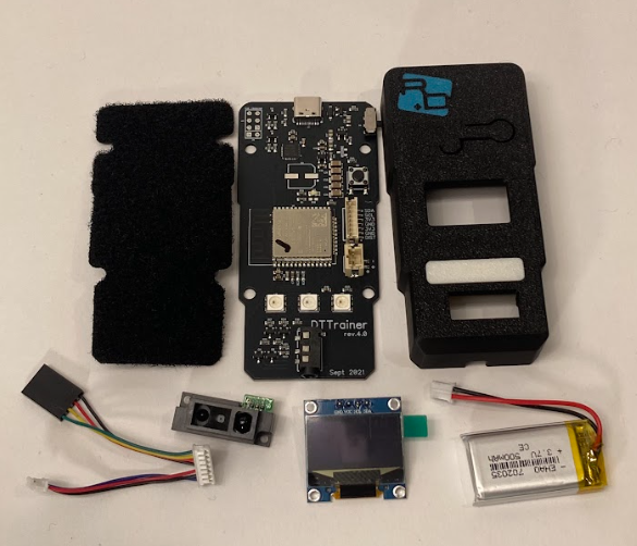
DTT build kit. -
Confirm the PCB, loop velcro, and housing are ready.
Confirm the DTT loop velcro is installed on the PCB before continuing.
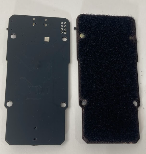
Raw PCB and velcro PCB. 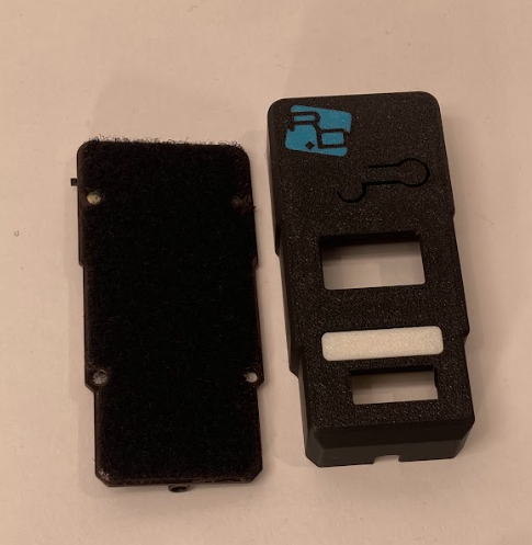
PCB with trainer case. -
Inspect the inside of the trainer case.
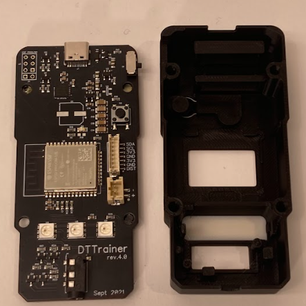
Inside of the trainer case. -
Clean and prepare before assembly.
Gently torch inside of the 3D housing to remove filament strands. Flash the PCB before assembly.
Assembly Steps
-
Install the screen.
Remove the film from the screen. Bend the ribbon gently inwards. Align the screen with the registration features and glue it into place with hot glue. Ensure the hot glue does not block the button arm.
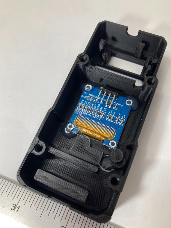
Screen installed in the case. -
Install the sensor.
Use a screwdriver to gently insert the sensor into the casing, pressing on the silver screws to add force without breaking the plastic. Make sure the sensor lays flush with the casing. Glue it into place with hot glue.
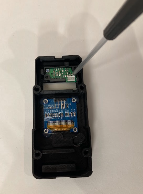
Press on the silver screws while inserting the sensor. 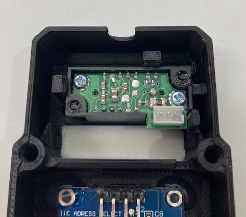
Sensor installed flush with the casing. -
Install the battery.
Insert the battery writing-side down. Run a bead of glue along the top bar to secure it in place.
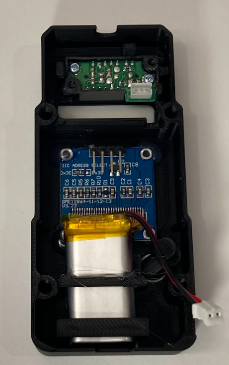
Battery installed writing-side down. -
Connect the screen and sensor harness.
Slide the black harness connector over the screen pins as shown. Clip the white connector into the sensor.
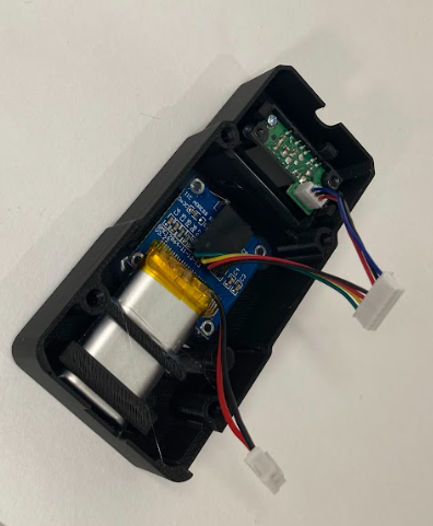
Screen pins and sensor connected to the harness. -
Connect the harness to the PCB.
Clip the harness into the PCB using the appropriate connectors.
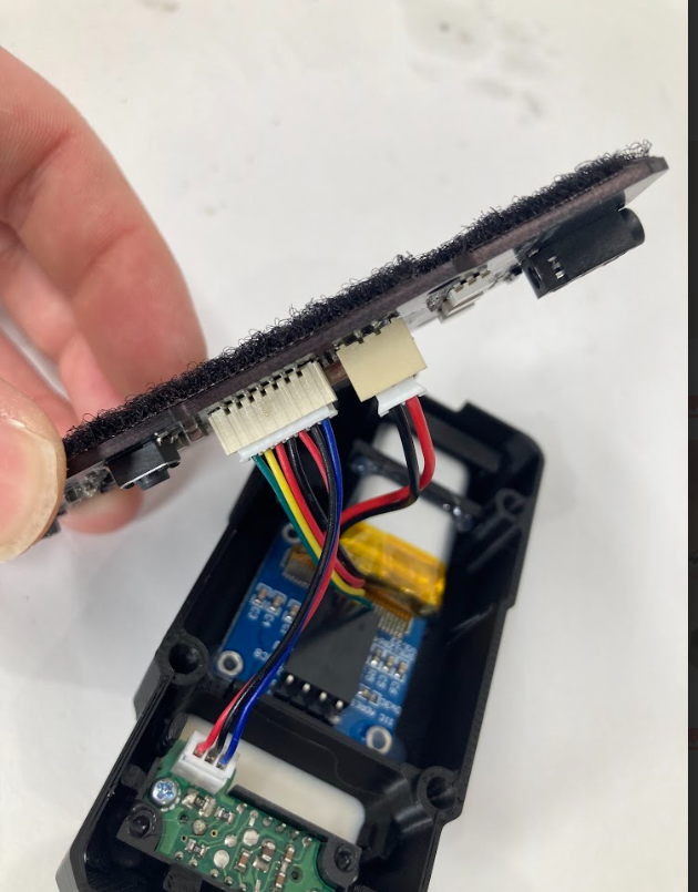
Harness connected to the PCB. -
Route the wires.
Route the wires around the peg as shown, and push the wires deeper into the housing, avoiding the button and other pinch points.
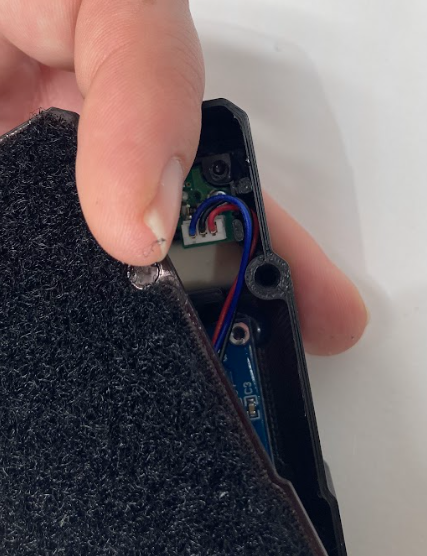
Wires routed around the peg. -
Fasten the PCB to the trainer case.
Use the screwdriver to fasten the PCB to the trainer case.
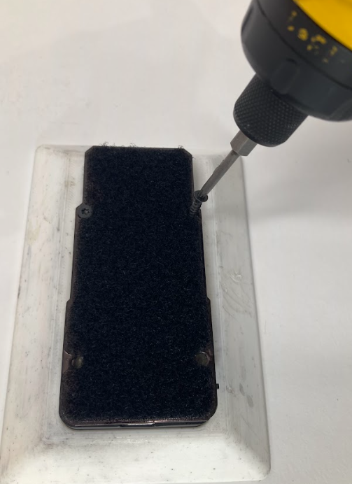
Fasten the PCB to the trainer case.
Final Assembly
- Confirm the screen is glued in place and the button arm is not blocked.
- Confirm the sensor is flush with the casing and glued in place.
- Confirm the battery is secured writing-side down.
- Confirm the harness is connected to the screen, sensor, and PCB.
- Confirm wires are routed around the peg and pushed away from the button and pinch points.
- Confirm the PCB is fastened to the trainer case with the four
0408LTFBscrews.
QC Checklist
- PCB was flashed before assembly.
- Interior filament strands were removed from the 3D printed housing.
- Screen film was removed.
- Screen ribbon was bent gently inward.
- Screen was aligned with registration features.
- Hot glue does not block the button arm.
- Sensor lays flush with the casing.
- Sensor is glued in place.
- Battery is installed writing-side down.
- Battery is secured with glue along the top bar.
- Black harness connector is seated over the screen pins.
- White connector is clipped into the sensor.
- Harness is clipped into the PCB connectors.
- Wires are routed around the peg.
- Wires are pushed deeper into the housing and avoid the button and pinch points.
- PCB is fastened to the trainer case.